
Flexible, bendable and twistable terahertz waveguide

A terahertz, flexible technology, applied in the field of waveguide, can solve the problem of changing the attenuation of optical fiber

Active Publication Date: 2017-02-22
SPINNER
View PDF12 Cites 11 Cited by
  • Summary
  • Abstract
  • Description
  • Claims
  • Application Information

AI Technical Summary

Problems solved by technology

Therefore, the deformation of the tube body changes the attenuation of the fiber

Method used


Image

  • Flexible, bendable and twistable terahertz waveguide
  • Flexible, bendable and twistable terahertz waveguide
  • Flexible, bendable and twistable terahertz waveguide

Examples


Embodiment Construction

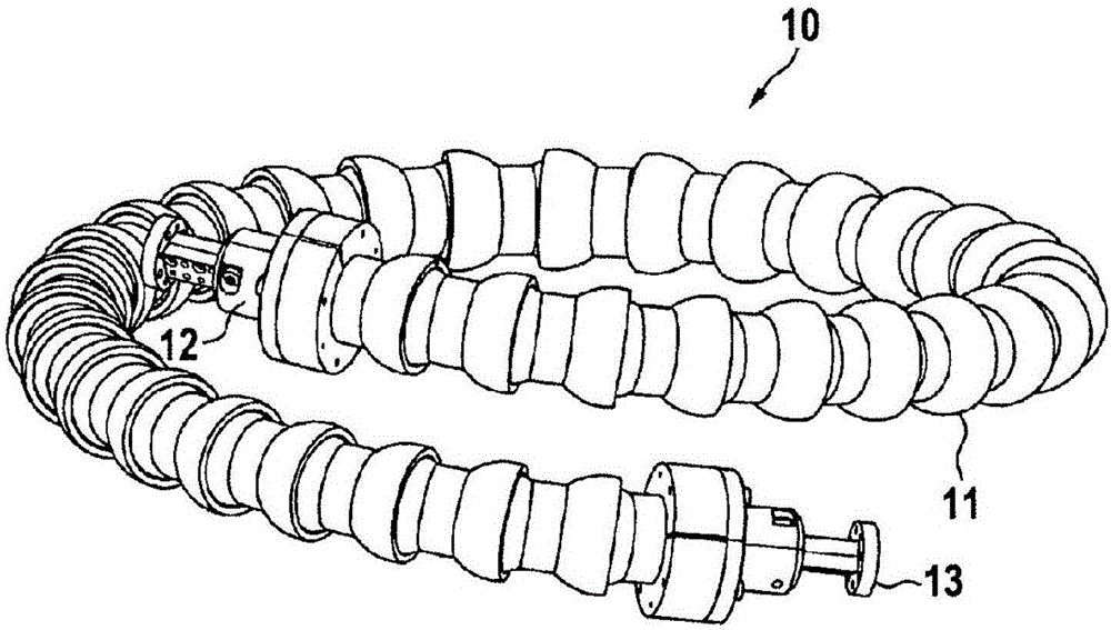
[0044] exist figure 1 In , a flexible waveguide assembly 10 is shown. It comprises a flexible waveguide cable 11 with a first waveguide flange connector 12 at its first end and a second waveguide flange connector 13 at its second end. In the illustrated embodiment, the flexible waveguide assembly is bent into a loop and twisted.

[0045] exist figure 2 middle, figure 1 The flexible waveguide assembly 10 is shown in straight form without being bent and twisted. Components here have the same figure 1 The examples in the different numbers of pipe body segments. Due to the flexible design, any number of body sections can be selected resulting in a wide range of lengths.

[0046] exist image 3 , showing figure 2 Cross-sectional view of the waveguide assembly. At the center of the assembly 10, there is a dielectric waveguide core 40 that defines the dielectric waveguide core axis by approximating an axis through the length of the dielectric waveguide core. The flexible ...


PUM


Abstract

A flexible and twistable terahertz waveguide assembly has a flexible waveguide cable with waveguide flange connectors at its ends. The flexible waveguide cable comprises a segmented tube of a plurality of tube segments which are connected to each other. The tube encloses a dielectric waveguide which is held by means of threads (filaments) at the center of the tube. The individual segments are tiltable and / or pivotable against each other, allowing bending and twisting of the waveguide cable.

Description

technical field [0001] The present invention relates to waveguides usable in the terahertz frequency range, which are flexible and can be bent and twisted several times to some extent. It is based on a dielectric waveguide. Background technique [0002] To guide electromagnetic waves in the terahertz range, waveguides are used in most cases. Such waveguides offer a sufficiently high transmission quality, but they have a rigid structure that cannot be bent. Especially when used in test setups, it is sometimes necessary to accommodate the mechanical tolerances of the signal inputs and outputs. At lower frequencies, when cables like coaxial cables can be used, cable routing between devices is very simple because the cables are flexible and adaptable to various needs. Additionally, hinge lines can be used. These are relatively expensive. [0003] German patent DE 32 34 699 C2 discloses a flexible waveguide for millimeter waves made of a corrugated tube body. The tubular bo...

Claims


Application Information

Patent Timeline
Patent Type & Authority Applications(China)
IPC IPC(8): H01P3/16G02B6/44H01P3/14
CPCH01P3/16G02B6/4461H01P3/14H01P1/02G02B6/443H01P1/04
Inventor H-U·尼克尔J·佐沃T·普罗克尔M·施米德
Owner SPINNER
Learn More