
Method and device for allocating channels

A channel and signal distribution technology, applied in the field of optical communication, can solve the problems of scattered channel distribution and serious filtering effect

Active Publication Date: 2019-12-13
HUAWEI TECH CO LTD
View PDF5 Cites 0 Cited by
  • Summary
  • Abstract
  • Description
  • Claims
  • Application Information

AI Technical Summary

Problems solved by technology

To solve the problem of severe filtering effect caused by scattered channel allocation

Method used


Image

  • Method and device for allocating channels
  • Method and device for allocating channels
  • Method and device for allocating channels

Examples


Embodiment Construction

[0099] The following will clearly and completely describe the technical solutions in the embodiments of the present invention with reference to the accompanying drawings in the embodiments of the present invention. Obviously, the described embodiments are only some, not all, embodiments of the present invention. Based on the embodiments of the present invention, all other embodiments obtained by persons of ordinary skill in the art without creative efforts fall within the protection scope of the present invention.

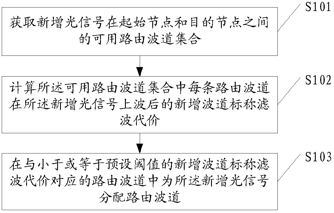
[0100] Please refer to figure 1 , is a schematic flowchart of a method for allocating channels in an embodiment of the present invention. In this embodiment, the method includes the following steps:

[0101] S101. Obtain a set of available routing channels between the originating node and the destination node of the newly added optical signal.

[0102] Before obtaining the set of available routing channels, the set of available paths between the originating node a...


PUM


Abstract

The embodiment of the present invention discloses a method for allocating channels, which includes: obtaining a set of available routing channels for newly added optical signals between the starting node and the destination node; The nominal filtering cost of the newly added channel after adding the wave to the newly added optical signal; the routing channel corresponding to the nominal filtering cost of the newly added channel that is less than or equal to the preset threshold value for the newly added optical signal Assign routing channels. The embodiment of the invention also discloses a device for allocating channels. By adopting the invention, the problem of severe filtering effect caused by dispersed channel allocation can be solved.

Description

technical field [0001] The invention relates to the technical field of optical communication, in particular to a method and device for allocating channels. Background technique [0002] In the existing WDM network, after a series of service lights, that is, a series of optical signals carrying service information arrive at a common path node, the service lights that wave down at this node and continue to flow to other nodes will Filter separation at the exit of the node. Each exit will have its own filter window to allow only the service light leaving the node through this exit, that is, the downwave. [0003] In the current channel allocation principle, the channel allocated by a service light has nothing to do with the next destination node of this service light. The destination nodes of the service lights on adjacent channels are generally different, and the service lights of the same destination node may be distributed in different channels at intervals. When the same...

Claims


Application Information

Patent Timeline
Patent Type & Authority Patents(China)
IPC IPC(8): H04L12/24
CPCH04L45/62
Inventor 夏丹青
Owner HUAWEI TECH CO LTD
Learn More