Dispensing cartridge with tortuous vent path

Inactive Publication Date: 2005-02-10
NORDSON CORP
View PDF14 Cites 73 Cited by
  • Summary
  • Abstract
  • Description
  • Claims
  • Application Information

AI Technical Summary

Problems solved by technology

Unfortunately, such a configuration complicates the configuration of the device making it relatively more difficult to fabricate.
Another problem encountered by such known dispensing cartridges relates to the use of an O-ring for sealing the piston within the dispensing cyli

Method used


Image

  • Dispensing cartridge with tortuous vent path
  • Dispensing cartridge with tortuous vent path
  • Dispensing cartridge with tortuous vent path

Examples


Embodiment Construction

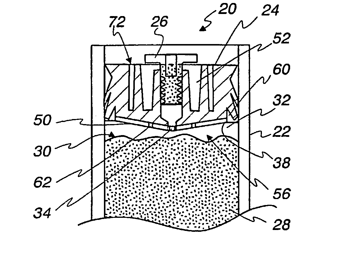
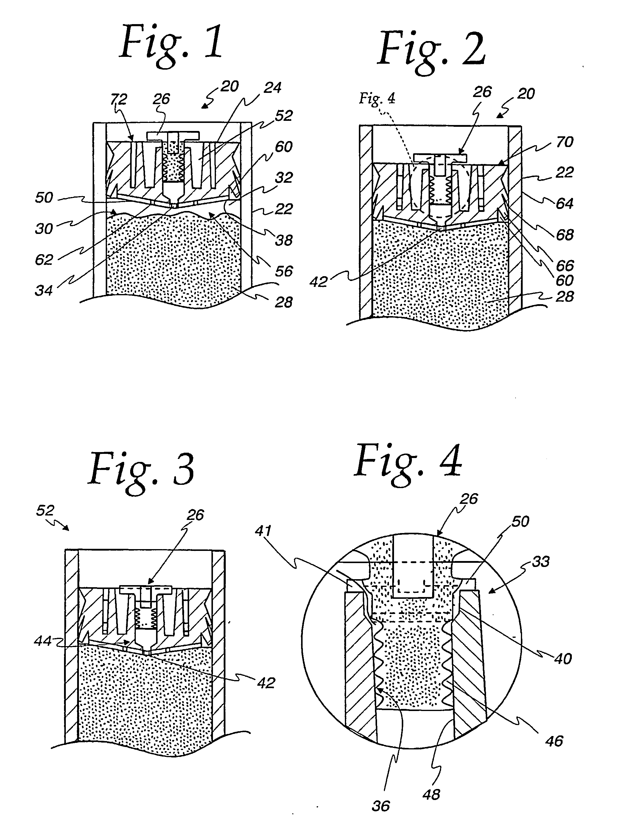
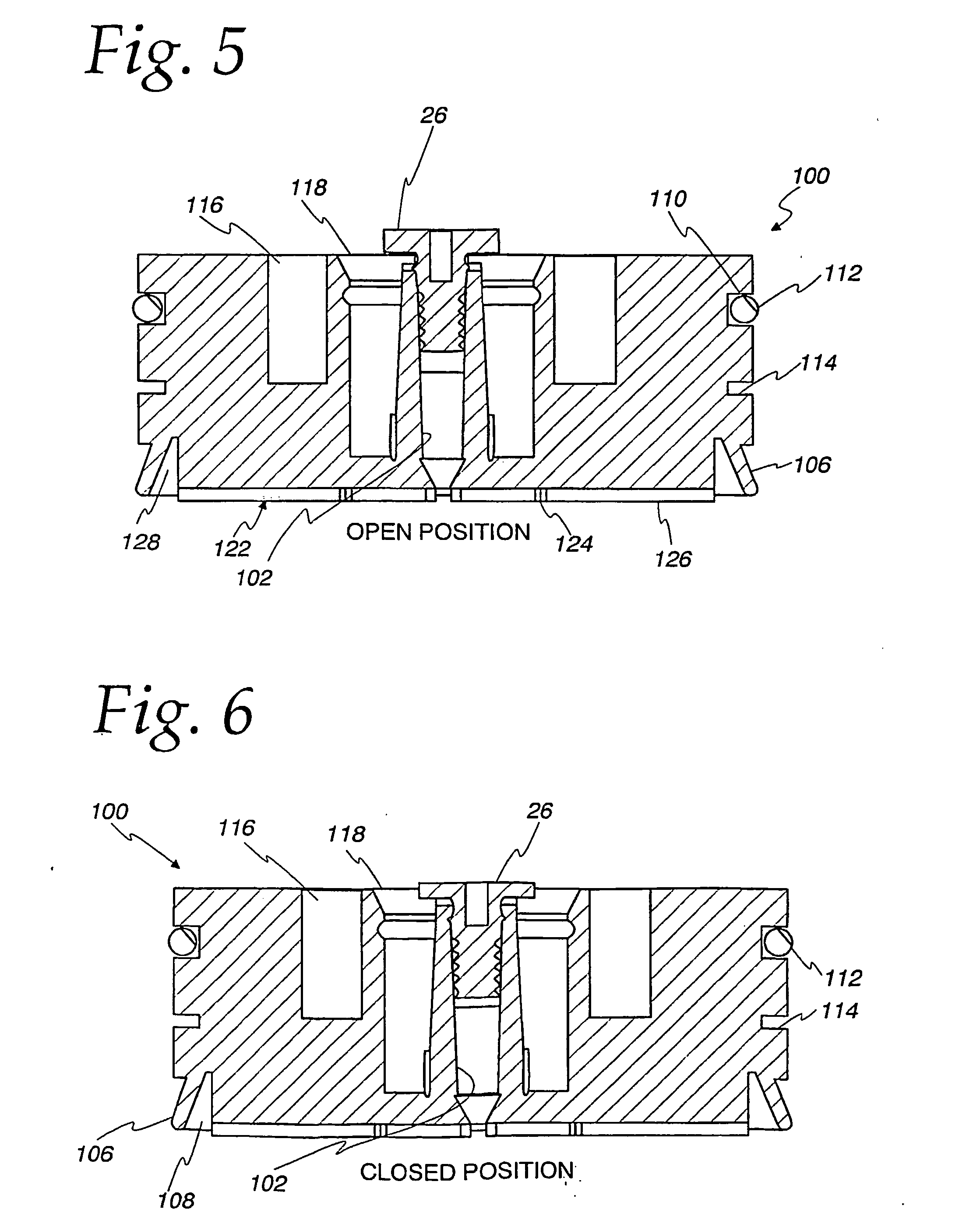
[0028] The present invention relates to a dispensing cartridge for relatively precise dispensing of fluids, for example, high viscosity fluids, such as caulking compounds. The dispensing cartridge includes a cylinder, a piston and a bleed plug. As will be discussed in more detail below, an air vent is provided in the piston and a bleed plug together form a tortuous path, for example, a spiral path, which allows air to freely escape but requires relatively high pressure (i.e. higher than normal operating pressure) in order for the fluid to backflow through the path, thus eliminating the need for an overflow chamber. In one embodiment of the invention, as illustrated in FIGS. 1-4, the piston is provided with the one or more sealing lips in lieu of an O-ring in order to further simplify the design, as well as totally eliminate known problems related to sealing the piston within the dispensing cartridge. By eliminating the O-ring, known problems associated with chemical attack of the O-...


PUM


Abstract

A dispensing cartridge for a relatively precise dispensing of various fluids having a relatively wide range of viscosities is disclosed. The dispensing cartridge in accordance with the present invention is relatively simpler in configuration than known dispensing cartridges while minimizing leakage of the fluid and eliminating problems associated with chemical attack of the O-ring by the fluid in the dispensing cylinder. In particular, the dispensing cartridge in accordance with the present invention includes a cylinder; a piston with a central bore and a bleed plug. In order to simplify the design, the air vent is configured as a tortuous path, for example, a spiral path, defined by a spiral bleed plug, which in a pre-staged position, allows air to freely escape along the spiral path along the circumference of the plug. As the piston contacts the fluid, the forward motion of piston is resisted by the high back pressure created by the small effective diameter and relatively long length of the spiral path. Once the piston contacts the fluid, the spiral plug is pushed into the piston closing the spiral path. By controlling the fluid flow by way of a tortuous path, the amount of fluid backflow through the piston is minimized if not eliminated, thus eliminating the need for an annular overflow chamber, thereby simplifying the design of the piston. In order to minimize problems related to the sealing of the piston within the dispensing cartridge, the piston may be provided with one or more radially extending sealing lips. These sealing lips are used in lieu of or in conjunction with an O-ring. The sealing lips further simplify the design by eliminating the O-ring as well as the need for an annular chamber adjacent thereto as well as problems relating to chemical attack of the O-ring by the fluid within the dispensing cylinder. In an alternative embodiment for use that is particularly adapted with non-aggressive fluids, the piston is provided with a single sealing lip and an O-ring.

Description

BACKGROUND OF THE INVENTION [0001] 1. Field of the Invention [0002] The present invention relates to a dispensing cartridge for relatively precise dispensing of various fluids having a relatively wide range of viscosities, the cartridge including a cylinder, a piston with a central bore and a bleed plug, the central bore and bleed plug configured to provide a tortuous path to prevent backflow of the fluid under normal operating conditions, thereby eliminating the need for an overflow chamber. The piston is further configured with one or more annular sealing lips for sealing the piston within the cylinder, thereby eliminating the need for an O-ring forming a single seal configuration. Alternatively, for use, inter alia, with non-aggressive fluids, the piston may be configured with one or more sealing lips and an O-ring forming a multiple seal configuration. [0003] 2. Description of the Prior Art [0004] Dispensing cartridges for relatively precise dispensing of fluids are known in the...

Claims


Application Information

Patent Timeline
IPC IPC(8): B05C17/005B65D83/00G01F11/06
CPCB05C17/00576B65D83/0005B05C17/00579
Inventor BRENNAN, ROBERT CHARLES
Owner NORDSON CORP
Why Eureka
Try Eureka