
Controlled voltage filter

A technology of capacitors and voltage sources, applied in the field of filter devices, can solve problems such as inconvenience

Active Publication Date: 2012-05-16
ROBERT BOSCH GMBH
View PDF6 Cites 0 Cited by
  • Summary
  • Abstract
  • Description
  • Claims
  • Application Information

AI Technical Summary

Problems solved by technology

Interference signals are perceptible and inconvenient to the user, especially in loads that generate acoustic or optical output signals

Method used


Image

  • Controlled voltage filter
  • Controlled voltage filter
  • Controlled voltage filter

Examples


Embodiment Construction

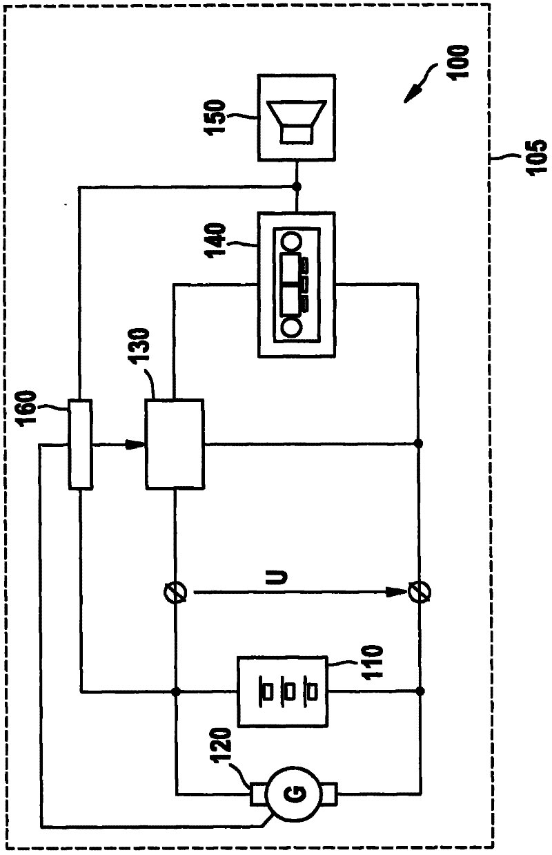
[0020] figure 1 A schematic diagram of an on-board electrical circuit 100 of a motor vehicle 105 is shown. Motor vehicle 105 may be, for example, a motor vehicle, in particular a sedan. To provide the supply voltage U, a battery 110 and a generator 120 are provided. During operation of motor vehicle 105 , generator 120 is driven by an internal combustion engine (not shown) and supplies a voltage with which battery 110 can be charged. The battery 110 is the preferred power source in the onboard electrical circuit 100 if the generator 120 is not driven by the internal combustion engine. The filter element 130 processes the supply voltage U and supplies the processed voltage to the audio device 140 . The audio device 140 generates an audio signal and provides the audio signal to the speaker 150 .

[0021] Control device 160 is connected to generator 120 , battery 110 and supply voltage U at generator 120 as well as the audio signal between audio system 140 and loudspeaker 150...


PUM


Abstract

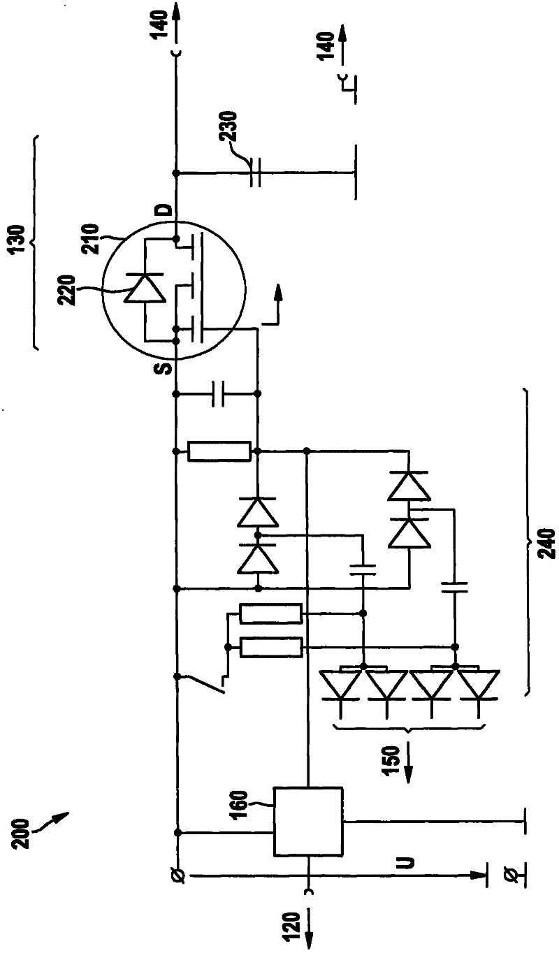
The present invention relates to a filtering device which is used for filtering an interfering signal from a power supply voltage. The power supply voltage is supplied to an electric load from a voltage source. The filtering device comprises the following components: a capacitor which is connected with the load in parallel, a diode which is connected between the power supply voltage and the capacitor in a conduction direction, and a variable resistor which is connected with the diode in parallel. Furthermore the controlled voltage filter is provided with a control device which controls the variable resistor according to the value of the power supply voltage.

Description

technical field [0001] The invention relates to a filter device and a method for filtering out interference signals from a supply voltage. Background technique [0002] Electrical loads generally require a supply voltage that is relatively free of interfering signals. Interference signals are perceptible and inconvenient to the user, especially in loads that generate acoustic or optical output signals. Some such devices include protection circuits that completely or partially shut down the device if the mains voltage does not meet predefined criteria. Such criteria may be overvoltage or undervoltage or interference signals in a predetermined frequency band. In complex environments, such as in motor vehicles, there is often a filter circuit between the electrical load and the supply voltage in order to process the supply voltage appropriately for the electrical load. [0003] Such a filter is disclosed in EP 1121749 B1 which is controlled according to the power absorbed by...

Claims


Application Information

Patent Timeline
Patent Type & Authority Applications(China)
IPC IPC(8): H02M1/15
CPCH02M1/12H02M1/14
Inventor J·富尔曼
Owner ROBERT BOSCH GMBH
Learn More