
Ionization detector via spark plug coil shorting primary inductance

A detector and spark plug technology, which is applied to the field of ionization detectors by short-circuiting the spark plug coils of the primary inductance, can solve the problems that the ionization detectors cannot be directly connected, etc.

Active Publication Date: 2021-02-05
BOARD OF TRUSTEES OPERATING MICHIGAN STATE UNIV
View PDF12 Cites 0 Cited by
  • Summary
  • Abstract
  • Description
  • Claims
  • Application Information

AI Technical Summary

Problems solved by technology

Therefore, ionization detectors cannot be connected directly to the spark plug terminals

Method used


Image

  • Ionization detector via spark plug coil shorting primary inductance
  • Ionization detector via spark plug coil shorting primary inductance
  • Ionization detector via spark plug coil shorting primary inductance

Examples


Embodiment Construction

[0019] Ionization detectors for detecting gas ionization in internal combustion engines detect the ionization current flowing through the ends of the spark plug. By routing the ionization current through the secondary winding of the ignition coil, a first-order low-pass filter is created between the ionization detector and the spark plug, resulting in an attenuation of the ionization signal indicative of the ionization current.

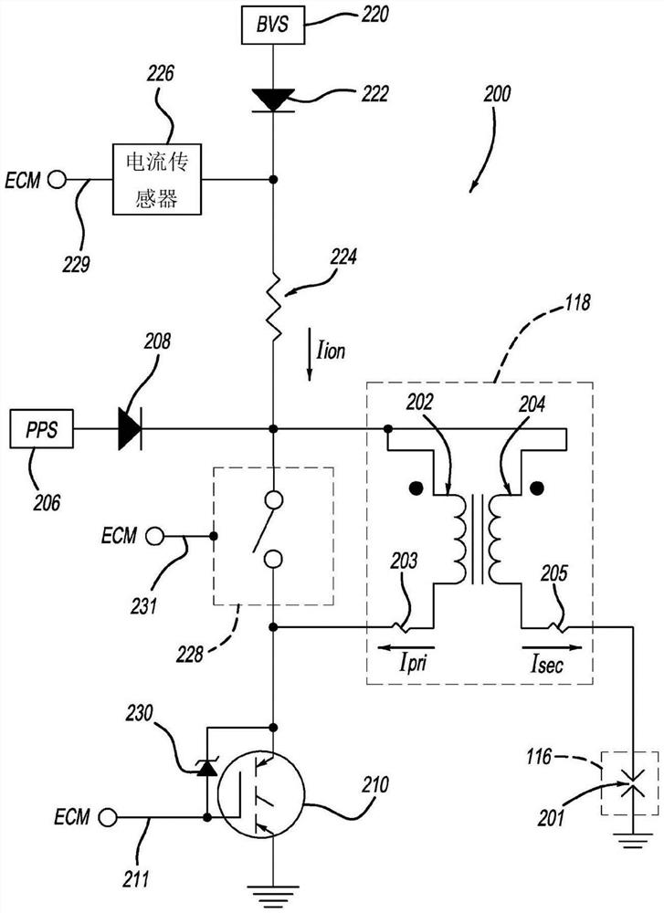
[0020] The disclosed ionization detector is configured to short the inductance of the ignition coil during the combustion phase of the engine. More specifically, the ionization detector shorts the inductance of the primary winding to effectively lower the impedance of the secondary winding and thus reduce the attenuation of the ionization signal.

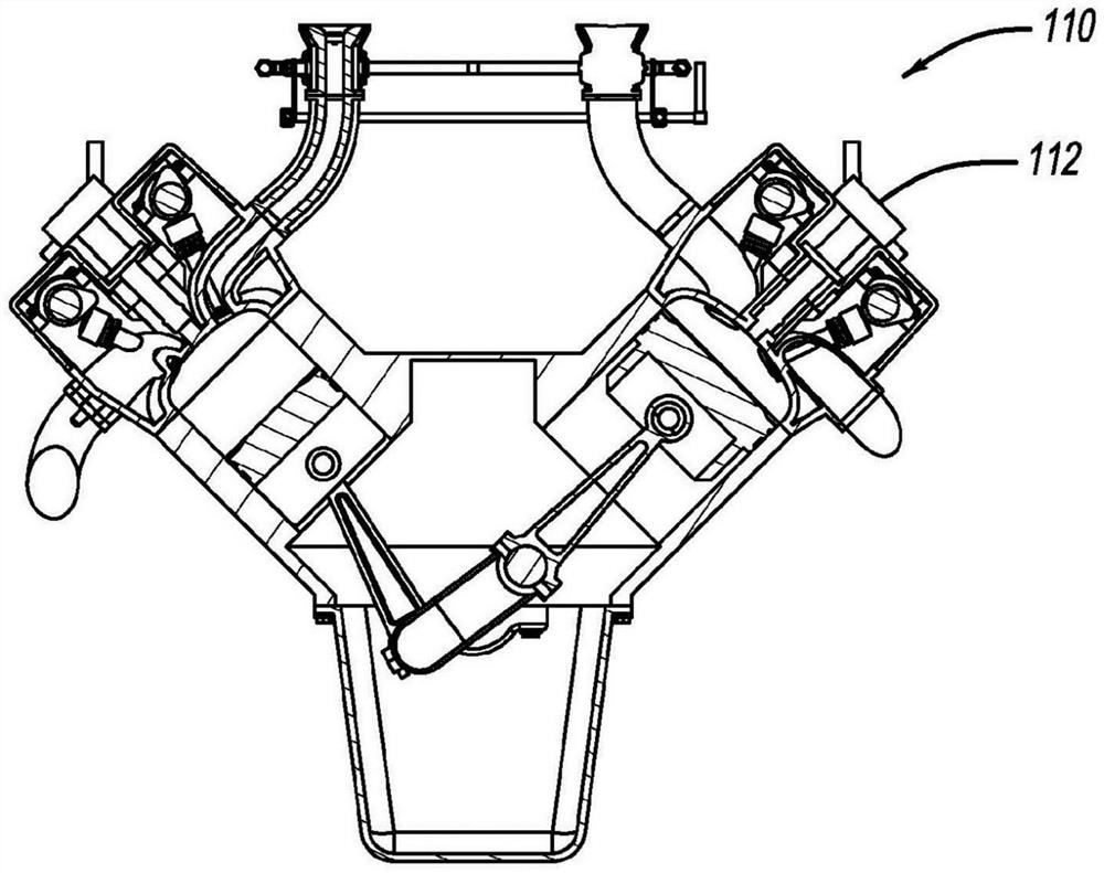
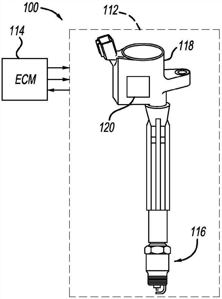
[0021] The present disclosure will now be described with reference to the accompanying drawings. Figure 1A with 1B A spark ignition system 100 is illustrated for an internal combustion engine 110 applica...


PUM


Abstract

An ionization detector (120) reduces filtering effects of an ignition coil (118) inductance by shorting the inductance of a primary winding (202) of the ignition coil (118). The ionization detector (120) includes a bias voltage source (220) and an inductance controlled switch (228). A bias voltage source (220) supplies a voltage across the electrical gap of the spark plug (116) for detecting ionization within the combustion chamber. An inductance control switch (228) is electrically connected in parallel with the primary winding (202) of the ignition coil (118) and is operable to short the inductance of the primary winding (202).

Description

[0001] Cross References to Related Applications [0002] This application claims priority to US Provisional Application Serial No. 62 / 205,022, filed August 14, 2015, which is hereby incorporated by reference. technical field [0003] The present disclosure relates to the detection of ionization of gases in internal combustion engines by measuring the ionization current through the secondary winding of a high inductance ignition coil. Background technique [0004] This section provides background information related to the disclosure in this application which is not necessarily prior art. [0005] A spark ignition engine includes a spark plug that protrudes into the engine's combustion chamber and provides an insulated electrode ground with a fixed spark gap. The ignition coil provides the energy needed for the electrical current to form an arc across the spark gap, igniting the air-fuel mixture in the combustion chamber and causing combustion. [0006] During the combusti...

Claims


Application Information

Patent Timeline
Patent Type & Authority Patents(China)
IPC IPC(8): F02P3/04F02P17/12H01F38/12F02D35/02G01L23/22F02P13/00H01T15/00H01T13/58
CPCF02P3/0435F02P13/00F02D35/021H01F38/12H01T13/58H01T15/00F02P2017/128G01L23/223F02P17/12G01N27/626
Inventor 朱国明凯文·莫兰
Owner BOARD OF TRUSTEES OPERATING MICHIGAN STATE UNIV
Learn More