High-power high-capacity lithium ion battery and preparation method thereof

A lithium-ion battery, high-capacity technology, which is applied in the manufacture of electrolyte batteries, secondary batteries, non-aqueous electrolyte batteries, etc. Lowering, improving safety, avoiding direct contact effects

Active Publication Date: 2017-03-01
BEIJING HAWAGA POWER STORAGE TECH
View PDF5 Cites 36 Cited by
  • Summary
  • Abstract
  • Description
  • Claims
  • Application Information

AI Technical Summary

Problems solved by technology

Therefore, the existing power lithium-ion battery structure design is difficult to simultaneously meet the needs of the battery's instantaneous high-power output and large-capacity storage.

Method used


Image

  • High-power high-capacity lithium ion battery and preparation method thereof
  • High-power high-capacity lithium ion battery and preparation method thereof
  • High-power high-capacity lithium ion battery and preparation method thereof

Examples


Embodiment 1

[0044] This embodiment provides a method for preparing a high-power and large-capacity lithium-ion battery with a stacked structure:

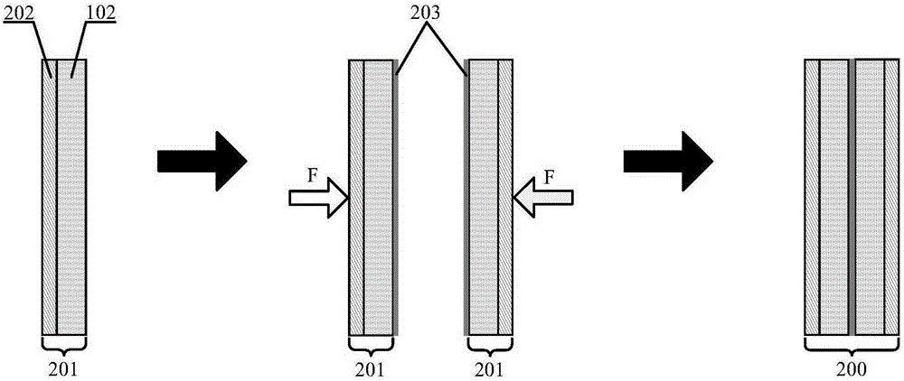
[0045] (1) Preparation of positive electrode sheet: In this embodiment, the porous positive electrode current collector 202 is a mixture of conductive filler and binder, the conductive filler is lithium-containing alloy powder, the binder is polyethylene oxide, and the positive electrode active material is lithium iron phosphate. , the conductive agent is selected from conductive graphite, and the binder is selected from polytetrafluoroethylene, wherein the mass ratio of lithium iron phosphate: conductive graphite: polytetrafluoroethylene is 78:20:2, and the positive electrode solvent is added to form a slurry after being stirred evenly. The plate is coated on one side of the mixture layer of conductive filler and binder, and after drying and pressing, a porous current-collecting positive electrode layer 201 is obtained, wherein the thickness of...

Embodiment 2

[0050] This embodiment provides a method for preparing a winding structure square high-power and large-capacity lithium-ion battery:

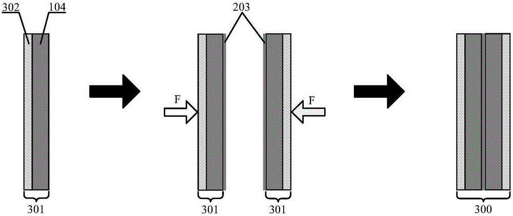
[0051] (1) Preparation of positive electrode sheet: In this embodiment, the porous positive electrode current collector 202 is made of porous aluminum foam layer, the positive electrode active material is made of lithium manganese phosphate, the conductive agent is made of carbon black, and the binder is made of polyethylene oxide, wherein lithium manganese phosphate : Carbon black: The mass ratio of polyethylene oxide is 90:9:1, and the positive electrode solvent is added to form a slurry after stirring evenly, and is coated on one side of the porous aluminum foam layer by thermal spraying, and the porous aggregate is obtained after drying and pressing. Flow the positive electrode layer 201, wherein the thickness of the coating, that is, the positive electrode material layer 102 is 800 μm, and then uniformly prepare a layer of nano-conductive l...


PUM

PropertyMeasurementUnit
thicknessaaaaaaaaaa
thicknessaaaaaaaaaa
thicknessaaaaaaaaaa

Abstract

The invention provides a high-power high-capacity lithium ion battery and a preparation method thereof. by changing the structure of electrodes and placement position of current collectors in existing lithium ion battery, an electrode material layer is arranged between two layers of current collectors to form an electrode, and positive and negative current collectors are respectively positioned at two sides of a diaphragm instead of being positioned inside the electrode material layer. According to the structure, the battery electrode layer is close to a reaction area for porous current collector, and there is always a low-internal-resistance area. Thus, the battery can meet requirement of instantaneous high-power operation. Meanwhile, thickness of the electrode layer can be greatly increased, and the requirement of a battery on large capacity can be met. Therefore, the contradiction that the increase of battery capacity leads to instantaneous power coastdown of a battery is effectively solved. As the porous current collector is arranged between the electrode layer and the diaphragm, direct contact between the electrode material layer and the diaphragm is avoided, the internal short-circuited risk caused by positive and negative active particles and a nano-conducting layer entering the diaphragm is reduced, and safety of the battery is raised.

Description

technical field [0001] The invention relates to the technical field of power batteries, in particular to a high-power and large-capacity lithium-ion secondary battery. Background technique [0002] Lithium-ion battery is a new type of high-energy battery with lithium-intercalated compounds as positive and negative electrode materials. Compared with lead-acid batteries and nickel-metal hydride batteries, it has a series of advantages such as high specific energy, high voltage, small self-discharge, good cycle performance and long life. Advantages, more and more people's attention. In recent years, lithium-ion battery technology has achieved rapid development and has begun to be used in electric vehicles. [0003] In order to improve the driving ability of electric vehicles, lithium-ion batteries, as the power source of electric vehicles, have high requirements for their storage capacity per unit volume and instantaneous high power output. For example, the higher the power s...

Claims


Application Information

Patent Timeline
Patent Type & Authority Applications(China)
IPC IPC(8): H01M10/0525H01M4/80H01M10/058
CPCH01M4/80H01M10/0525H01M10/058Y02E60/10Y02P70/50
Inventor 陈永翀张晓虎何颖源张艳萍张萍
Owner BEIJING HAWAGA POWER STORAGE TECH
Why Eureka
Try Eureka