Quick withdrawing mold

A mold and fast technology, which is applied in the field of rapid draft molds, can solve the problems of mold sticking together and inconvenient drafting, and achieve the effect of avoiding damage to the workpiece

Active Publication Date: 2017-03-08
CHONGQING DEYUN MOLD MFG
View PDF5 Cites 0 Cited by
  • Summary
  • Abstract
  • Description
  • Claims
  • Application Information

AI Technical Summary

Problems solved by technology

[0002] Industrial workpieces, especially trapezoidal shaft workpieces, are often formed by pouring pouring fluid directly through the mold, but after the workpiece is cooled, it is easy to stick to the mold directly, and it is inconvenient to pull out the mold

Method used


Image

  • Quick withdrawing mold
  • Quick withdrawing mold
  • Quick withdrawing mold

Examples


Embodiment Construction

[0018] In order to make the technical means, creative features, purpose and effect of the present invention more clear and easy to understand, the following in conjunction with the attached Figure 1~3 The present invention is further elaborated with specific embodiment:

[0019] "Up", "Down", "Left" and "Right" mentioned in the present invention are attached figure 1 Up, down, left and right shown.

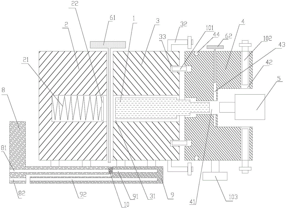
[0020] The present invention proposes a quick draft mold, which includes a stepped shaft workpiece 1, and also includes a first mold 2, a second mold 3, a third mold 4 and a knocking mechanism 5 connected in sequence; the first mold 2, the second The mold 3 and the third mold 4 have a first film cavity, a second film cavity 31 and a third film cavity 41 in turn, and the second film cavity 31 and the third film cavity 41 communicate with each other and are connected to the stepped shaft workpiece 1 Adapted, the first film cavity corresponds to the second film cavity 31, the thir...


PUM


Abstract

The invention provides a quick withdrawing mold. The quick withdrawing mold comprises a stepped shaft workpiece. The quick withdrawing mold further comprises a first mold body, a second mold body, a third mold body and a knocking mechanism which are sequentially connected. The first mold body, the second mold body and the third mold body are sequentially provided with a first mold cavity, a second mold cavity and a third mold cavity correspondingly. The second mold cavity and the third mold cavity communicate with each other and then are matched with the stepped shaft workpiece. The first mold cavity corresponds to the second mold cavity. The third mold cavity further comprises a knocking mechanism stretching hole, and the knocking portion of the knocking mechanism is located in the knocking mechanism stretching hole, corresponds to the third mold cavity and can knock the stepped shaft workpiece. A first spring is arranged in the second mold cavity and connected with a buffer plate. According to the quick withdrawing mold, the second mold cavity and the third mold cavity communicate with each other and then form a continuously-through mold cavity body, and pouring liquid is poured into the mold cavity body so that the stepped shaft workpiece can be formed. After the stepped shaft workpiece is formed and cooled, the right end of the stepped shaft workpiece is continuously knocked with the knocking mechanism, and accordingly the stepped shaft workpiece can be squeezed out of the left end of the second mold cavity quickly.

Description

technical field [0001] The invention relates to the field of molds, in particular to a quick draft mold. Background technique [0002] Industrial workpieces, especially trapezoidal shaft workpieces, are often formed by direct pouring of casting fluid through molds. However, after the workpiece is cooled, it is easy to stick to the mold directly, and it is inconvenient to pull out the mold. Contents of the invention [0003] The problem to be solved by the present invention is to provide a quick draft mold for convenient drafting in view of the above-mentioned deficiencies in the prior art. [0004] In order to achieve the above object, the present invention adopts the following technical solutions: a quick draft mold, including a stepped shaft workpiece, and also includes a first mold, a second mold, a third mold and a knocking mechanism connected in sequence; the first The mold, the second mold and the third mold have a first film cavity, a second film cavity and a third...

Claims


Application Information

Patent Timeline
Patent Type & Authority Applications(China)
IPC IPC(8): B29C39/26B29C39/36
CPCB29C39/26B29C39/36
Inventor 李朝安
Owner CHONGQING DEYUN MOLD MFG
Why Eureka
Try Eureka