High-accuracy paper printing equipment

A printing equipment and high-precision technology, which is applied in the direction of printing, printing machines, general parts of printing machinery, etc., can solve the problems of printing accuracy decline and achieve the effect of ensuring rationality

Inactive Publication Date: 2017-03-08
马飞
View PDF0 Cites 3 Cited by
  • Summary
  • Abstract
  • Description
  • Claims
  • Application Information

AI Technical Summary

Problems solved by technology

Therefore, the printing workshop often effectively controls the internal temperature and humidity, but the equipment that works in a long-term cycle will generate a certain amount of heat during the working process, which will have a certain impact on the surface temperature of the paper being printed, and seriously cause printing accuracy. decline

Method used


Image

  • High-accuracy paper printing equipment
  • High-accuracy paper printing equipment
  • High-accuracy paper printing equipment

Examples


Embodiment 1

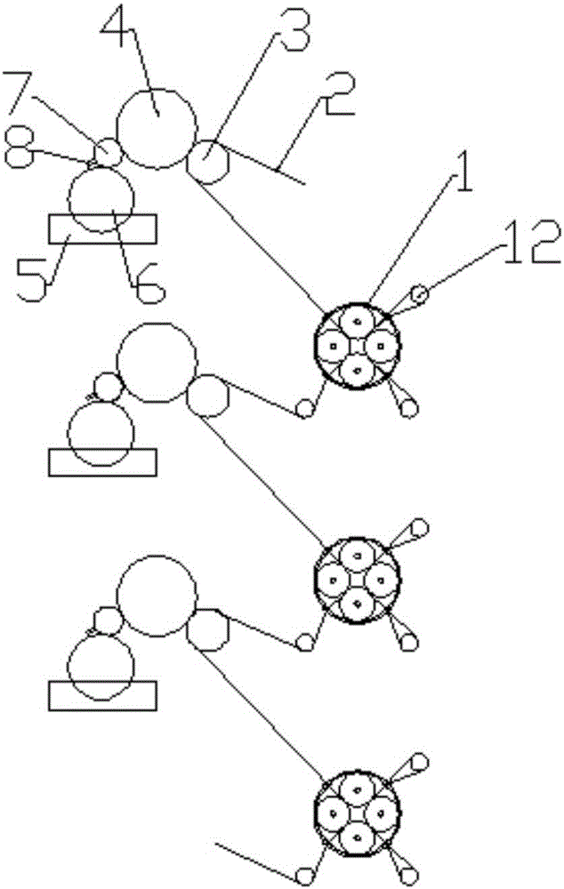
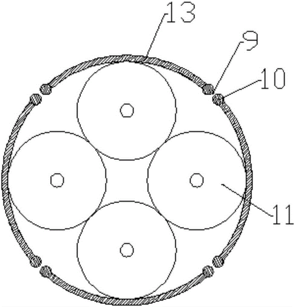
[0027] Such as figure 1 and image 3 As shown, a high-precision paper printing equipment includes a number of constant temperature and humidity boxes 1 arranged side by side, a number of printing parts and printing paper 2 arranged on the side of the constant temperature and humidity box 1; wherein the constant temperature and humidity box 1 has a cylindrical structure, and the interior The temperature is controlled at 15-18°C, the humidity is controlled at 60-70% RH, and the constant temperature and humidity box 1 mainly includes a casing 13 and four rolling shafts 11 uniformly arranged inside the casing 13, and the side walls of the adjacent rolling shafts 11 The shortest distance between them is 0.5-2 mm; there are several through grooves 9 on the side wall of the shell 13 along the direction of the central axis, and a cylindrical bar 10 is respectively arranged on the side walls of the two ends of the through groove 9 along the direction of the central axis of the shell, a...

Embodiment 2

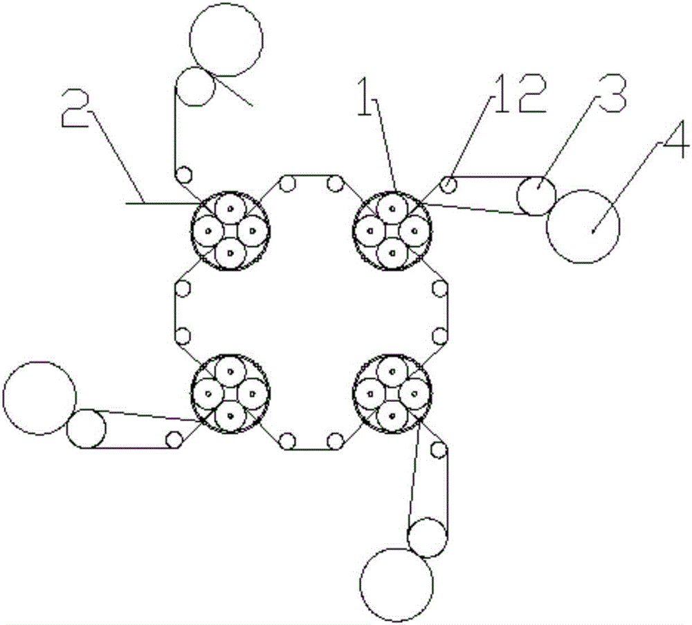
[0030] Such as figure 2 As shown, the only difference between this embodiment and Embodiment 1 is that several constant temperature and humidity chambers 1 are arranged in a circular distribution; when working, the printing paper 2 passes through the middle of the impression roller 3 and the printing plate cylinder 4 and then enters In the constant temperature and humidity chamber 1, at this moment, after directly passing through a rolling shaft 11, it passes out and enters the next constant temperature and humidity chamber 1, and then enters the next printing unit again for printing, and so on until all printing is completed.

[0031] The above two embodiments are the two distribution methods that are often used. During work, it can also be considered in multiple aspects such as site layout requirements, paper flexibility, external temperature and humidity, so as to achieve a more reasonable and effective distribution and maximize work efficiency.


PUM


Abstract

The invention discloses high-accuracy paper printing equipment. The high-accuracy paper printing equipment comprises a plurality of constant-temperature moisturizing boxes, printing components and printing paper, wherein each constant-temperature moisturizing box is of a cylindrical structure, and mainly comprises a housing and a plurality of rolling shafts which are uniformly distributed in the housing; a plurality of through grooves are arranged in the sidewall of the housing along a central axis direction, and a cylindrical bar is arranged on the sidewalls of the two ends of each through groove along the central axis direction of the housing respectively; each printing component comprises an impression roller, a printing plate roller, an ink container, an ink foundation roll, an anilox roll and a scraping plate which are arranged outside the corresponding constant-temperature moisturizing box; and the printing paper is provided with an input end, and the middle part is sequentially wound on the rolling shafts, guide rods and the impression rollers. According to the high-accuracy paper printing equipment disclosed by the invention, constant-temperature moisturizing devices are additionally arranged in traditional printing equipment and used for adjusting the temperature and humidity of the surface of the paper in a short time, thus achieving an accuracy requirement of printing.

Description

technical field [0001] The invention relates to the technical field of printing equipment, in particular to a high-precision paper printing equipment. Background technique [0002] A printing press is a machine that prints text and images. Modern printing machines are generally composed of plate loading, ink application, embossing, paper feeding (including folding) and other mechanisms. Its working principle is: first make the printing plate of the text and image to be printed, install it on the printing machine, and then apply the ink to the place where the text and image are on the printing plate manually or by the printing machine, and then transfer it directly or indirectly Print onto paper or other substrates such as textiles, sheet metal, plastic, leather, wood, glass, and ceramics to reproduce the same print as the printing plate. The invention and development of the printing press played an important role in the spread of human civilization and culture. [0003] I...

Claims


Application Information

Patent Timeline
Patent Type & Authority Applications(China)
IPC IPC(8): B41F23/02
CPCB41F23/02
Inventor 马飞
Owner 马飞
Why Eureka
Try Eureka