Upper prefabricated member-lower prefabricated member butting structure and upper prefabricated member-lower prefabricated member combination face grouting method

A technology of prefabricated parts and joint surfaces, applied to building components, building structures, walls, etc., can solve problems affecting structural safety, cavities appearing on the joint surface of upper and lower floors, and air cannot be discharged, so as to ensure safety and eliminate cavities Effect

Inactive Publication Date: 2017-03-08
深圳市鹏城建筑集团有限公司 +1
View PDF8 Cites 2 Cited by
  • Summary
  • Abstract
  • Description
  • Claims
  • Application Information

AI Technical Summary

Problems solved by technology

[0003] The invention overcomes the disadvantages in the prior art that when the joint surfaces of the upper and lower layers of shear walls and frame columns are filled with grout, the air in the cavity cannot be discharged, which eventually leads to the occurrence of cavities in the upper and lower layers of the joint surface, which affects the structural safety, and provides Provides a butt joint structure of the upper and lower prefabricated parts, and also provides a method for grouting the joint surface of the upper and lower prefabricated parts

Method used


Image

  • Upper prefabricated member-lower prefabricated member butting structure and upper prefabricated member-lower prefabricated member combination face grouting method
  • Upper prefabricated member-lower prefabricated member butting structure and upper prefabricated member-lower prefabricated member combination face grouting method
  • Upper prefabricated member-lower prefabricated member butting structure and upper prefabricated member-lower prefabricated member combination face grouting method

Examples


Embodiment Construction

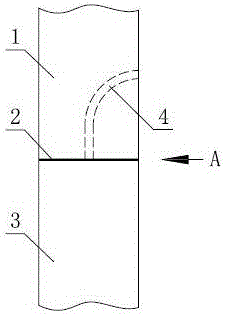
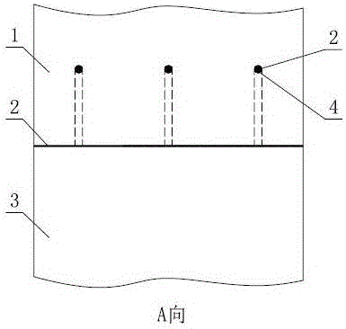
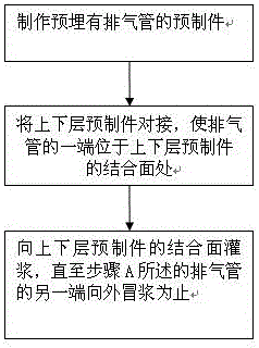
[0021] as attached figure 1 , 2 As shown, the butt joint structure of the upper and lower prefabricated parts in this embodiment includes two prefabricated parts that are connected to the upper and lower layers, that is, the upper prefabricated part 1 and the lower prefabricated part 3, and the joint surfaces of the upper and lower prefabricated parts are filled with grouting . At least one preform, that is, the upper preform 1 is provided with an exhaust channel, one end of the exhaust channel extends outside the joint surface of the preform, and the other end of the exhaust channel extends outside the other surfaces of the preform. The preferred exhaust channel in this embodiment is the built-in exhaust pipe 4 or exhaust groove. During the actual pouring process, the exhaust pipe 4 has been pre-buried in the upper prefabricated part 1 . When the concrete 2 is poured into the joint surface of the upper prefabricated part 1 and the lower prefabricated part 3, the gas in the...


PUM


Abstract

The invention provides an upper prefabricated member-lower prefabricated member butting structure and an upper prefabricated member-lower prefabricated member combination face grouting method, aiming to overcome the effect on structural safety due to the fact that failure to exhaust air in a hollow cavity leads to cavities formed in upper layer-lower layer combination faces finally when the combination faces of upper and lower shear walls and upper and lower frame columns are grouted. The upper prefabricated member-lower prefabricated member butting structure comprises an upper prefabricated member and a lower prefabricated member which are butted, the combination face of the two prefabricated members is grouted, and at least one of the prefabricated members is provided with an exhaust passage with one end extending out of the combination face of the prefabricated member and the other end extending out of other surfaces thereof. The upper prefabricated member-lower prefabricated member butting structure and the upper prefabricated member-lower prefabricated member combination face grouting method have the advantages that both structural safety and construction quality are guaranteed, and the butting structure and the grouting method are suitable for grouting of the combination face of the upper and lower prefabricated members.

Description

[0001] The invention relates to the field of building industrialization, in particular to a butt joint structure of upper and lower prefabricated parts and a method for grouting the joint surfaces of the upper and lower prefabricated parts. Background technique [0002] During the installation of prefabricated shear walls and frame columns, when the joint surfaces of the upper and lower shear walls and frame columns are filled with grout, since the air in the cavity cannot be discharged, the internal air pressure will also increase during the continuous grouting process. It is getting bigger and bigger, which will eventually lead to cavities in the joint surface of the upper and lower layers, which will affect the structural safety. Contents of the invention [0003] The invention overcomes the disadvantages in the prior art that when the joint surfaces of the upper and lower layers of shear walls and frame columns are filled with grout, the air in the cavity cannot be discha...

Claims


Application Information

Patent Timeline
Patent Type & Authority Applications(China)
IPC IPC(8): E04B2/56
CPCE04B2/56
Inventor 费权李宏伟
Owner 深圳市鹏城建筑集团有限公司
Why Eureka
Try Eureka