Novel section bar corner position pulling sheet, pulling set and novel section bar corner position system

A technology for pulling the code piece and horizontally pulling the code piece, which is applied in the field of profile corner position system and assembly accessories, can solve problems such as sealing, and achieve the effect of not easy to turn over.

Inactive Publication Date: 2017-03-08
朱成祥
View PDF6 Cites 0 Cited by
  • Summary
  • Abstract
  • Description
  • Claims
  • Application Information

AI Technical Summary

Problems solved by technology

[0004] However, although the design of the set of pull code pieces, pull code sets and profile corner position system is relatively simple, it still has some room for improvement: in the cavity of the profile corner position, there are often some parts that need to be adjusted with tools. structure, at this time it may be necessary to extend the tool from the outside to the inside of the corner of the profile, but the hook section of the pull piece seals the tool's entrance and exit. If an avoidance hole is designed in the hook section, the pull piece There is no landing hook

Method used


Image

  • Novel section bar corner position pulling sheet, pulling set and novel section bar corner position system
  • Novel section bar corner position pulling sheet, pulling set and novel section bar corner position system
  • Novel section bar corner position pulling sheet, pulling set and novel section bar corner position system

Examples


Embodiment 1

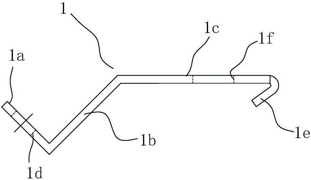
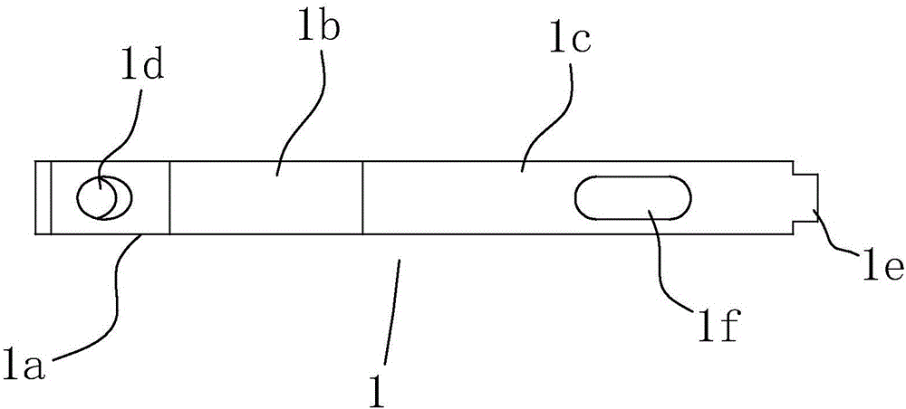
[0025] refer to figure 1 with figure 2 , a new type of profile corner pull piece, including a pull piece main body 1, the pull piece main body 1 is in the shape of a narrow and long strip as a whole, and is sequentially bent from the head end to the tail end to form a connecting section 1a, a transition section 1b, a hook pull Section 1c, connecting section 1a, transition section 1b, and hook section 1c are integrated, and the connecting section 1a has a connecting hole 1d. The direction of the head end of the pulling chip main body 1 is straight or bent, and the direction of the straight or bent direction of the pull hook 1e is opposite to the bending direction of the connecting section 1a. That is to say, if the inflection direction of the connecting section is taken as the upper direction, the drag hook extends obliquely downward. In this way, a structure convenient for tightening the screw and making the drag hook pull the profile can be conveniently constructed.

[002...

Embodiment 2

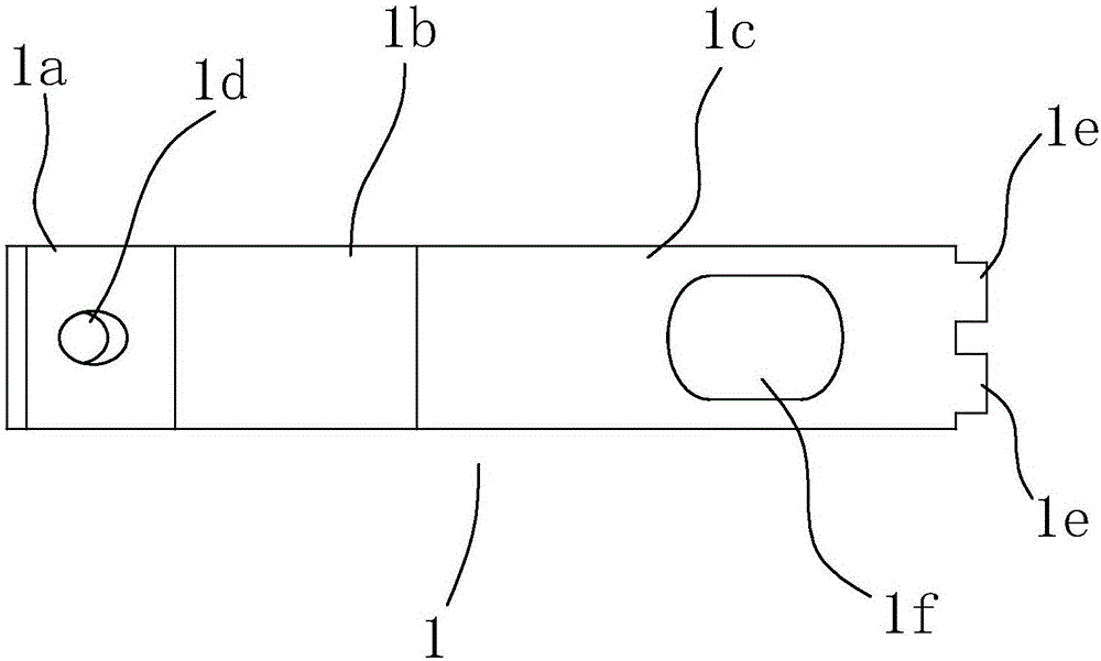
[0030] refer to image 3 , The shape and structure of the pulling piece of embodiment 2 is basically the same as that of embodiment 1, but the number of pulling hooks 1e is more than two, and they are arranged side by side at the end of the hook pulling section 1c. This kind of structure generally appears when the pull piece is wide. Since a single pull hook may not have enough pulling force, more than two pull hooks are designed to meet the tension balance requirements.

Embodiment 3

[0031] Embodiment 3 is about the specific implementation of the pull code group at the corner of the profile.

[0032] Example 3:

[0033] refer to Figure 4 , the profile corner pull code group includes a horizontal pull code 2 and a vertical pull code 3, and the horizontal pull code 2 is the above-mentioned new profile corner pull code, with the bottom surface of the horizontal pull code 2 connecting section It is a mirror image symmetry plane, the overall shape and structure of the vertical pull code sheet 3 is mirror image symmetrical to the horizontal pull code sheet 2, and a connecting screw 7 passes through the connecting hole of the horizontal pull code sheet 2 and the vertical pull code sheet 3 at the same time to connect the horizontal pull code sheet 2 Connect with the vertical pull code 3. Of course, after the connection, the connecting screw 7 locks the two pull code pieces, and there are multiple options for cooperating with nuts and directly processing threade...


PUM


Abstract

The invention discloses a novel section bar corner position pulling sheet, a pulling set and a section bar corner position system. The puling sheet comprises a pulling sheet main body. The pulling sheet main body is in a long stripped shape on the whole and bent into a connection section, a transition section and a hook-drawing section from the head end to the tail end; a connection hole is formed in the connection section; the least tail end of the hook-drawing section is provided with more than one draw hook; and straight-extending or bending directions of the draw hooks are opposite to an inflection direction of the connection section. The section bar corner position pulling set comprises a transverse pulling sheet and a vertical pulling sheet, and the two pulling sheets are connected together via a connection screw. The section bar corner position system comprises the section bar corner position pulling set, a transverse frame and a vertical frame, wherein the transverse frame is connected with the vertical frame via the draw hooks by the section bar corner position pulling set. Punching of the draw hook on the plate surface of the hook-drawing section can be unnecessary, and a preserved position can be applied for an empty-avoiding hole; and the section bar combination is uneasy to turn over. The novel section bar corner position pulling sheet, the pulling set and the section bar corner position system can be widely applied to assembling work of section bar corner position of doors and windows.

Description

technical field [0001] The invention relates to the field of door and window profile assembly structures, in particular to a profile corner position system in the assembly structure and assembly accessories used in the system. Background technique [0002] In the profile assembly structure of doors and windows, there will inevitably be corner positions, such as the right-angle corner positions of doors and windows, etc., which are generally made of two profiles (or combined profiles) at a certain angle, obliquely cutting off the profile ends and adding Spliced ​​by connecting accessories. If the cutting angle is 45 degrees, standard right-angle frames for doors and windows can be spliced ​​and assembled. However, since the profiles are independent of each other, how to ensure the alignment of the intersection lines of the two, the alignment of the cutting bevels, and the leveling of the profile surfaces during splicing is a big problem. [0003] The inventor once proposed ...

Claims


Application Information

Patent Timeline
Patent Type & Authority Applications(China)
IPC IPC(8): E06B3/98
CPCE06B3/98
Inventor 朱成祥
Owner 朱成祥
Why Eureka
Try Eureka