
Mixed-flow air conditioner

An air-conditioning and mixed-flow technology, which is applied in air-conditioning systems, airflow control components, space heating and ventilation, etc., can solve the problems of slow cooling and heating speed, high cost of air-conditioning, and ineffective effects, so as to improve the performance and comfort of air-conditioning degree, cost reduction effect

Active Publication Date: 2017-03-08
QINGDAO HAIER SMART TECH R & D CO LTD +1
View PDF6 Cites 15 Cited by
  • Summary
  • Abstract
  • Description
  • Claims
  • Application Information

AI Technical Summary

Problems solved by technology

However, the effect of this air-drawing air conditioner to relieve the overall temperature in the room is not obvious, and the cooling and / or heating speed is relatively slow
At the same time, this kind of drainage air conditioner also requires a comprehensive transformation of the air duct structure and air outlet of the air conditioner, resulting in an oversized air conditioner and high air conditioning costs

Method used


Image

  • Mixed-flow air conditioner
  • Mixed-flow air conditioner
  • Mixed-flow air conditioner

Examples


Embodiment Construction

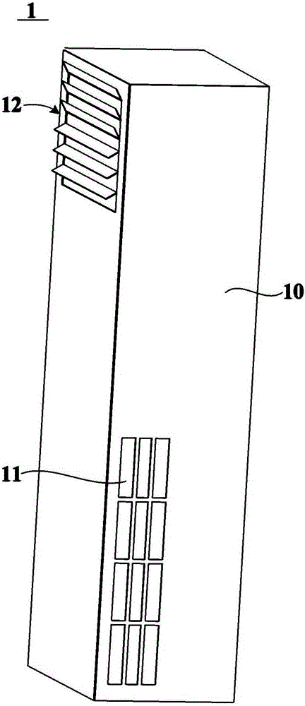
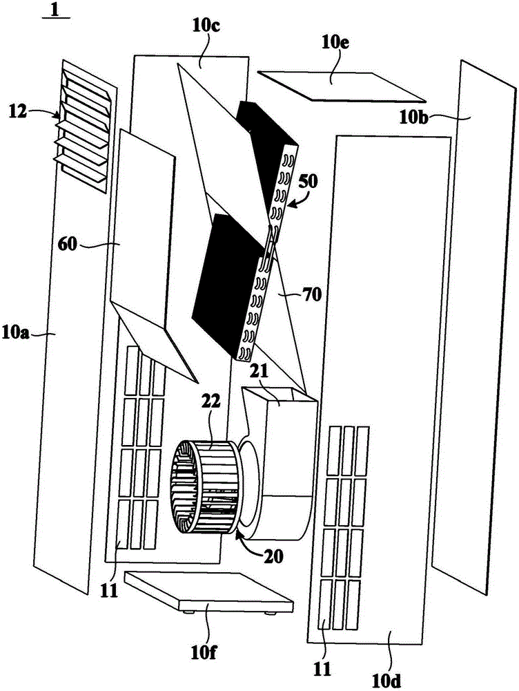
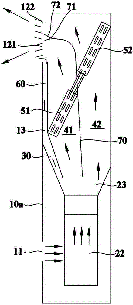
[0036] figure 1 is a schematic structural diagram of a mixed-flow air conditioner 1 according to an embodiment of the present invention, figure 2 is a schematic exploded view of the mixed flow air conditioner 1 according to an embodiment of the present invention. see figure 1 with figure 2 , the mixed-flow air conditioner 1 includes a casing 10 having an air inlet 11 and an air outlet 12, the air inlet 11 is used to introduce air from the environment, and the air outlet 12 is used to send air back to the environment. Specifically, the casing 10 may include a front side panel 10a, a rear side panel 10b, side panels 10c and 10d, an upper top panel 10e and a lower bottom panel 10f, the front side panel 10a, the rear side panel 10b, and the side panels 10c, which are independent from each other. and 10d, the upper top plate 10e and the lower bottom plate 10f are assembled and connected by fixing members such as screws to form a housing 10 with an internal space. Certainly, t...


PUM


Abstract

The invention relates to a mixed-flow air conditioner. The mixed-flow air conditioner comprises a shell as well as a draught fan, a heat exchange device, a through path, a first heat exchange air duct and a second heat exchange air duct which are arranged in the shell, wherein the shell is provided with an air inlet and an air outlet; the through path is configured to communicate the upstream part with the downstream part of the heat exchange device, thereby allowing air at the upstream part of the heat exchange device to directly flow to the downstream part of the heat exchange device through the through path; the first heat exchange air duct communicates with the through path, and is configured to allow part of air subjected to heat exchange in the heat exchange device to flow to the air outlet through the first heat exchange air duct for being mixed with air from the through path; then, the mixed air is blown into an environmental space along the first direction, thereby moderating the air outlet temperature at the air outlet of the mixed-flow air conditioner and improving the comfort of the mixed-flow air conditioner; the second heat exchange air duct is configured to allow part of the air subjected to heat exchange in the heat exchange device to flow to the air outlet through the second heat exchange air duct; and then the air is blown into the environmental space along the second direction, thereby quickly moderating the temperature in the environmental space.

Description

technical field [0001] The invention relates to household appliances, in particular to a mixed-flow air conditioner. Background technique [0002] The air duct structure of a common air conditioner in the existing market is generally composed of an air inlet, a centrifugal fan, an evaporator and an air outlet. Indoor air enters the interior of the air conditioner from the air inlet, and after being centrifugally accelerated by the centrifugal fan, the air passes through the evaporator for heat exchange, and the air after heat exchange is blown into the room through the air outlet. However, the temperature of the cool air blown out from the air outlet is too low and not soft enough, and it will cause discomfort to the user when blown on the body. [0003] In order to solve the above-mentioned technical problems, a drainage air conditioner has appeared in the prior art, which introduces a little indoor air at the air outlet of the air conditioner, and mixes it with the air af...

Claims


Application Information

Patent Timeline
IPC IPC(8): F24F1/00F24F13/02F24F13/06F24F13/30F24F13/08F24F13/22
CPCF24F1/0007F24F1/005F24F13/02F24F13/06F24F13/08F24F13/22F24F13/30F24F2013/221
Inventor 唐林强付松张立臣王晶晶刘德昌马壮
Owner QINGDAO HAIER SMART TECH R & D CO LTD
Learn More