Automatic recognition and conversion circuit for input end polarity of L/N line

An input terminal, automatic switching technology, applied in the field of emergency lighting, can solve problems such as misjudgment, and achieve the effect of wide application and flexibility

Inactive Publication Date: 2017-03-08
崔剑
View PDF13 Cites 2 Cited by
  • Summary
  • Abstract
  • Description
  • Claims
  • Application Information

AI Technical Summary

Problems solved by technology

As long as the circuit structure is given an opposite polarity voltage at the input, there will be misjudgment to trigger the emergency lighting function

Method used


Image

  • Automatic recognition and conversion circuit for input end polarity of L/N line
  • Automatic recognition and conversion circuit for input end polarity of L/N line
  • Automatic recognition and conversion circuit for input end polarity of L/N line

Examples


Embodiment 1

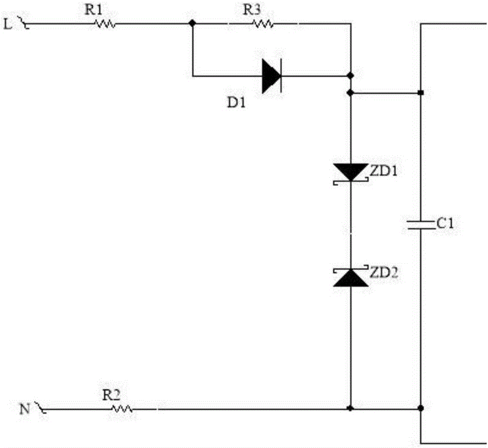
[0024] by figure 2 The circuit shown is an example, which is a rheostat half-bridge rectifying and limiting circuit composed of resistors R1, R2, R3, diode D1, voltage regulator tubes ZD1, ZD2 and capacitors. The circuit connection relationship is that the first end of the resistor R1 is connected to the live wire L end, the second end of the resistor R1 is connected to the first end of the resistor R3 and the forward conduction input end of the diode D1. The resistor R3 is connected in parallel with the diode D1, and the second terminal of the resistor R3 and the output terminal of the diode are connected to the forward conduction input terminal of the voltage regulator transistor ZD1. The voltage regulator tube ZD1 and the voltage regulator tube ZD2 are reversely connected, the output terminal of the voltage regulator tube ZD1 is connected to the output terminal of the voltage regulator tube ZD2, the input terminal of the voltage regulator tube ZD2 is connected to the secon...

Embodiment 2

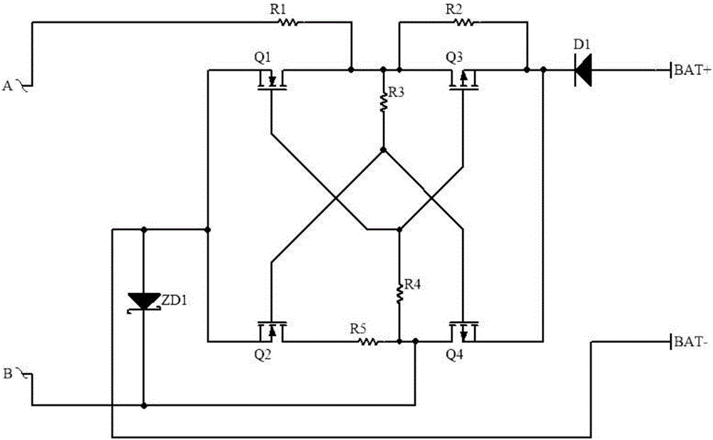
[0027] by image 3The circuit shown is an example, which is a bridge polarity conversion circuit composed of resistors R1, R2, R3, R4, R5, diode D1, voltage regulator tube ZD1, MOS tubes Q1, Q2, Q3, and Q4. The circuit connection relationship is that the first end of the resistor R1 is connected to the first output end A of the rheostat half-bridge rectifier limiting circuit, the second end of the resistor R1 is respectively connected to the drain of the MOS transistor Q1, and the first end of the resistor R3 , the drain of the MOS transistor Q3, and the first end of the resistor R2. The source of the MOS transistor Q1 is connected to the negative electrode BAT- of the battery, the input terminal of the regulator ZD1 and the source of the MOS transistor Q2; the gate of the MOS transistor Q1 is connected to the gate of the MOS transistor Q3 and the first end of the resistor R4. The second terminal of the resistor R3 is connected to the gate of the MOS transistor Q2 and the gat...

Embodiment 3

[0032] The rheostat half-bridge rectifying and limiting circuit and the bridge polarity changing circuit in Embodiment 1 and Embodiment 2 can be implemented independently in cooperation with their rectifying circuit or polarity changing circuit. This embodiment is a preferred embodiment of the combination of the rheostat half-bridge rectifying and limiting circuit and the bridge polarity changing circuit.

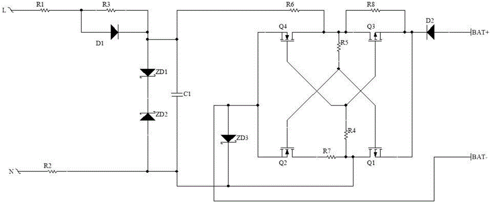
[0033] like figure 1 As shown, the two ends of the capacitor C1 in the rheostat half-bridge rectifying and limiting circuit are respectively used as two output ends. The output terminal of the capacitor C1 is connected to the first terminal of the resistor R6, and the second terminal of the capacitor C1 is connected to the output terminal of the regulator transistor ZD3, the second terminal of the resistor R7, the second terminal of the resistor R4 and the drain of the MOS transistor Q1.

[0034] According to its circuit principle, when the high-voltage alternating current...


PUM


Abstract

The invention discloses an automatic recognition and conversion circuit for input end polarity of an L/N line. The automatic recognition and conversion circuit consists of a half-bridge type rectifying and amplitude-limiting circuit and an automatic polarity recognition switching bridge type circuit; based on a pair of voltage-stabilizing tubes, the input ends of which are connected oppositely, and capacitors connected with the voltage-stabilizing tubes in parallel, a high-voltage alternating current is rectified into a direct current, and then is subjected to amplitude-limiting, so that the rectified voltage is reduced to a safe voltage; and based on a bridged MOS transistor, a back polar circuit is automatically switched to follow the polarity of an input voltage. The circuit can automatically recognize the L/N line polarity in a power grid circuit and can perform automatic adjustment. By adoption of the way, the problem that L/N lines have to be distinguished in assembling of similar products so as to prevent from dysfunction of the similar product caused by wrong wiring or voltage polarity interference from other electric appliance in the power grid can be avoided; and the product is more intelligent and can be more widely and flexibly applied.

Description

technical field [0001] The invention relates to the field of emergency lighting, in particular to an intelligent emergency lighting product with one lamp and multiple functions, which can be used as a general lighting product when the power supply is normal, and can automatically switch to emergency lighting function when the power grid is cut off. Background technique [0002] Existing emergency lighting fixtures with similar functions have strict requirements on the wiring of the L / N line of the power grid. There is a problem with abnormal function. This functional defect is determined by the defect in the circuit structure of this type of product itself. As long as the circuit structure is given an opposite polarity voltage at the input, there will be misjudgment to trigger the emergency lighting function. Contents of the invention [0003] The technical problem mainly solved by the present invention is to provide a circuit structure that can automatically identify th...

Claims


Application Information

Patent Timeline
Patent Type & Authority Applications(China)
IPC IPC(8): H02H11/00H02J9/02
CPCH02H11/003H02J9/02
Inventor 崔剑
Owner 崔剑
Why Eureka
Try Eureka