Vehicle fee charging method and apparatus

A technology of vehicle and vehicle identity, applied in the computer field, can solve the problems of long time for electronic card swiping, queuing and delay, and interference of vehicles beside the non-stop toll collection system.

Active Publication Date: 2017-03-15
TENCENT TECH (SHENZHEN) CO LTD
View PDF10 Cites 29 Cited by
  • Summary
  • Abstract
  • Description
  • Claims
  • Application Information

AI Technical Summary

Problems solved by technology

[0002] With the rapid increase of economic growth and the number of cars, the traditional way of manual charging has seriously affected the efficiency of cars passing through the toll booth, and computer electronic technology is often used to improve the charging method of vehicles
[0003] The existing vehicle charging method adopts electronic card swiping or microwave-specific short-range communication between the electronic tag on the vehicle and the microwave antenna on the lane of the toll station ETC (Electronic Toll Collection System, non-stop charging system), and uses computer networking technology to communicate with the bank. Fees are charged through the background settlement processing method, but electronic card swiping has a long time to take out the card, and card machine failures easily cause queues and delays, while the non-parking toll system has problems such as interference from side vehicles, and requires the construction of special car channels, which requires a large investment of resources and is complicated high degree

Method used


Image

  • Vehicle fee charging method and apparatus
  • Vehicle fee charging method and apparatus
  • Vehicle fee charging method and apparatus

Examples


Embodiment Construction

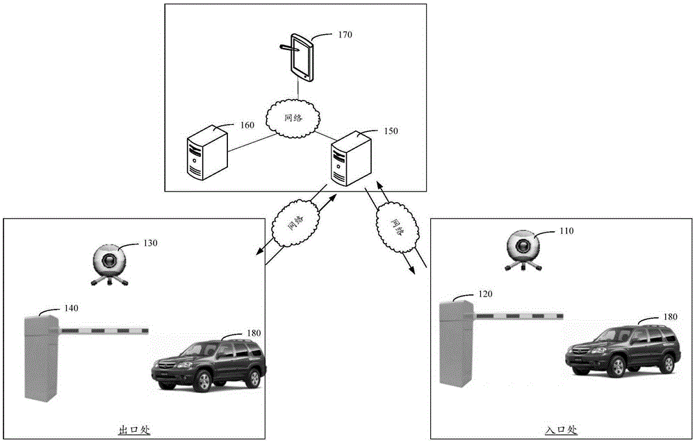
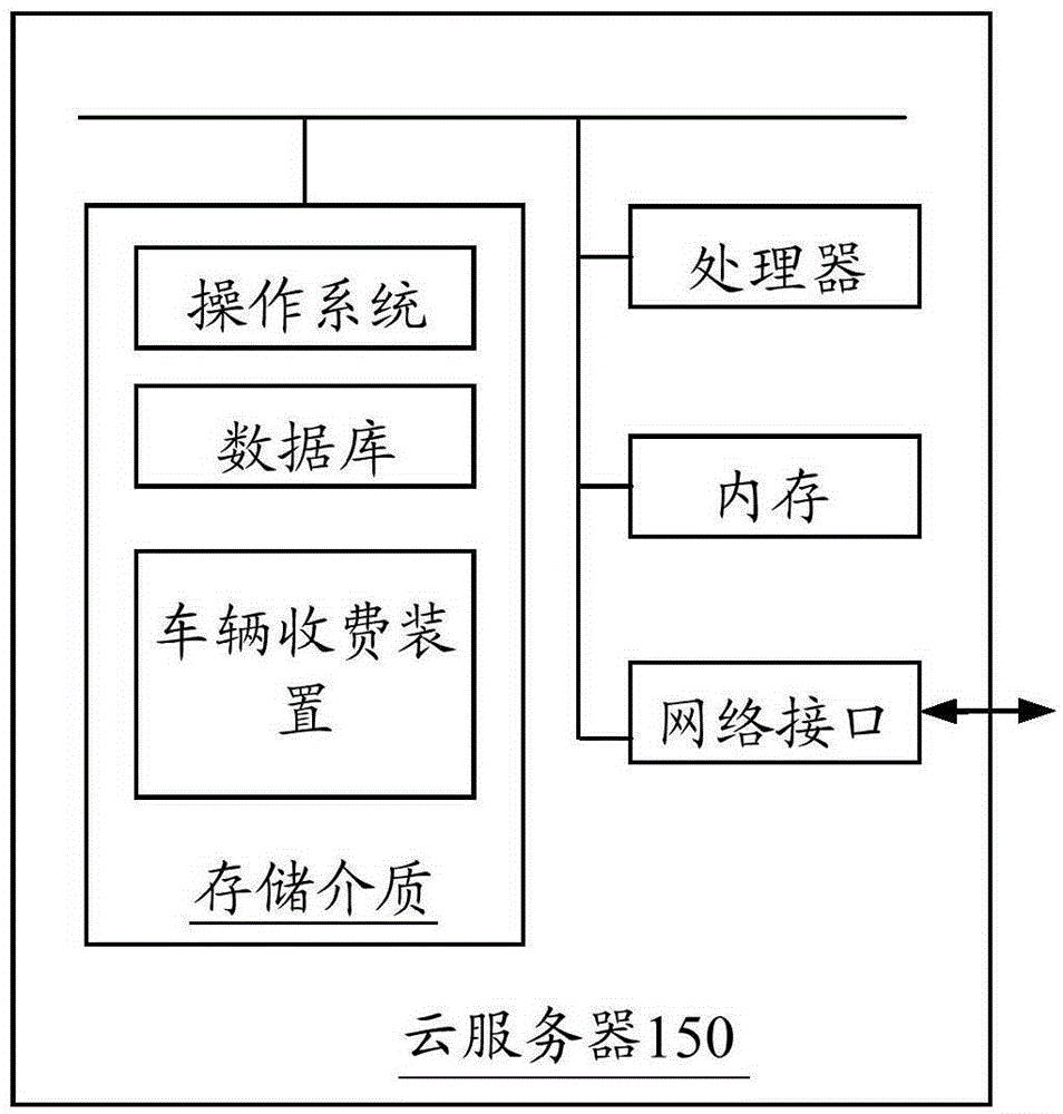
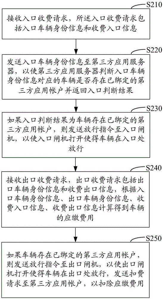
[0028] figure 1 It is an application environment diagram for the operation of the vehicle charging method in one embodiment. Such as figure 1 As shown, the application environment includes a video capture device 110, a video capture device 130, a gate 120, a gate 140, a cloud server 150, a third-party server 160 and a terminal 170, video capture devices 110 and 130, gates 120 and 140, The cloud server 150, the third-party server 160, and the terminal 170 can all communicate through the network. Vehicle S180 travels from the entrance to the exit.

[0029] The terminal 170 can be a smart phone, a tablet computer, a notebook computer, a desktop computer, etc., but is not limited thereto. The video capture devices 110 and 130 may be cameras, video recorders and other devices that can capture video or images. Turnstiles 120 and 140 are used to control the passage of vehicles, and cloud server 150 can respond to the request sent by video acquisition equipment 110 and 130, and se...


PUM


Abstract

The invention relates to a vehicle fee charging method and apparatus. The method comprises the following steps: receiving a fee charging request at an entrance including the vehicle identity information and the fee charging entrance information; transmitting the vehicle identity information at the entrance to a third party application server so that the third party application server is capable of determining whether the vehicle corresponding to the vehicle identity information at the entrance has a third party application bonded account or not and returning the determination result at the entrance; if the determination result at the entrance tells that the vehicle has the third party application bonded account, then sending the pass instruction to the toll gate at the entrance so as to open the gate for the vehicle to enter; and receiving a fee charging request at an exit including the vehicle identity information and the fee charging exit information. In the method and apparatus, according to the vehicle identity information at the entrance, the vehicle identity information at the exist, the toll gate entrance information and the toll gate exit information, the fees that the vehicle is supposed to pay are calculated; and if the vehicle has a third party application bonded account, a pass instruction is sent to the toll gate at the entrance so as to open the gate for the vehicle to enter and the fee subtraction request is sent to the third party application account so as to subtract the fees that the vehicle is supposed to pay. Therefore, the vehicle passing efficiency is increased.

Description

technical field [0001] The invention relates to the field of computer technology, in particular to a vehicle charging method and device. Background technique [0002] With the rapid increase of economic growth and the number of cars, the traditional way of manual toll collection has seriously affected the efficiency of cars passing through the toll booth, and computer electronic technology is often used to improve the way of toll collection of vehicles. [0003] The existing vehicle charging method adopts electronic card swiping or microwave dedicated short-range communication between the electronic tag on the vehicle and the microwave antenna on the lane of the toll station ETC (Electronic Toll Collection System, non-stop charging system), and uses computer networking technology to communicate with the bank. The background settlement process charges, but the electronic card swiping takes a long time to take out the card and the card machine malfunctions, which may easily ca...

Claims


Application Information

Patent Timeline
Patent Type & Authority Applications(China)
IPC IPC(8): G07B15/06
CPCG07B15/06
Inventor 张磊万超谢志杰张世鹏徐欣丁超辉毛华赵沫杨惠琴
Owner TENCENT TECH (SHENZHEN) CO LTD
Why Eureka
Try Eureka