The connection structure and clothing of components and wires

A technology of connection structure and plug-in structure, applied in the field of smart wear, can solve the problems of reducing comfort, cumbersomeness, increase in volume and weight of wearable devices, etc., and achieve the effect of avoiding exposure and sealing the connection.

Active Publication Date: 2019-12-03
ZHEJIANG HUAER TEXTILE TECH
View PDF6 Cites 0 Cited by
  • Summary
  • Abstract
  • Description
  • Claims
  • Application Information

AI Technical Summary

Problems solved by technology

[0003] However, the integrated design of components will increase the volume and weight of the wearable device, and it will bring obvious burden and foreign body feeling to the wearer when it is installed on the clothes, reducing the comfort.

Method used


Image

  • The connection structure and clothing of components and wires
  • The connection structure and clothing of components and wires
  • The connection structure and clothing of components and wires

Examples


Embodiment 1

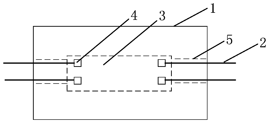
[0029] figure 1 Schematic diagram of the connection structure between components and wires provided by the embodiment of the present invention Figure 1 , the connection structure can be set on clothes as a wearable device. like figure 1 As shown, the connection structure between the component and the wire includes:

[0030] The component body 1 and the wire 2 form a cavity connection area 3 inside the component body 1, and at least one electrical signal terminal 4 is arranged in the cavity connection area 3, and the electrical signal terminal 4 is electrically connected to the internal circuit of the component body 1; A wire channel 5 is provided between the cavity connection area 3 and the outer wall of the element body 1 for the wire 2 to pass through; the wire 2 is connected to the electrical signal terminal 4, and the wire 2 leads to the outside of the element through the wire channel 5 .

[0031] Among them, the component body 1 is an independent component with certai...

Embodiment 2

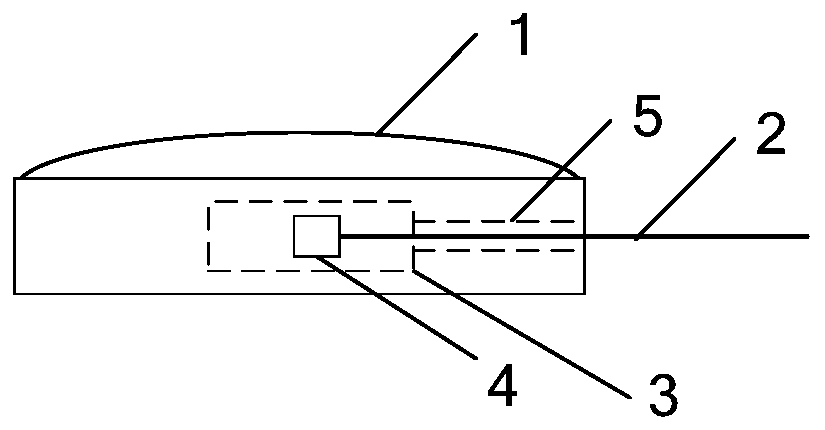
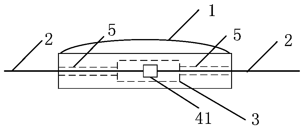
[0036] figure 2 and image 3 Schematic diagrams of other two connection structures between components and wires provided for the embodiments of the present invention, these two connection structures can be regarded as figure 1 The specific implementation of the shown structure embodiment. in contain figure 1 Based on all structural features shown, figure 2 and image 3 From the perspective of the layout of the wires in the wire channel, the connection structure of this embodiment will be described in detail.

[0037] Usually, when the interconnection relationship between components is relatively simple, and the electrical signal terminal drawn out of each component body 1 has only an interconnection relationship with one external component, it can be used figure 2 The connection structures shown enable the interconnection between elements. figure 2 The structure of can be regarded as one of the most basic connection structures.

[0038] figure 2Among them, each el...

Embodiment 3

[0049] Figure 4 The schematic diagram of the connection structure between the components and the wires provided by the embodiment of the present invention can be regarded as figure 1 The specific implementation of the shown structure embodiment. in contain figure 1 Based on all structural features shown, combined Figure 4 The connection structure of this embodiment is described in detail from the perspective of the specific connection manner between the components and the wires.

[0050] like Figure 4 In , the connection between the component and the wire can be fixed at one time by a similar welding method. This connection method does not need to be provided with an intermediate interface for plugging and unplugging wires to the electrical signal terminal 4, only the electrical pins of the electrical signal terminal 4 need to be exposed in the cavity connection area 3, and pre-installed in the cavity connection area 3 It is sufficient to leave the space occupied by th...


PUM


Abstract

Embodiments of the invention provide a connecting structure of an element and wires, and clothes. The connecting structure comprises an element body and the wires, wherein a hollow cavity connecting region is formed in the element body; at least one electric signal end is arranged in the hollow cavity connecting region; the electric signal end is electrically connected with an internal circuit of the element body; a wire channel for allowing each wire to pass through is formed between the hollow cavity connecting region and the outer wall of the element body; the wire is connected with the corresponding electric signal end; and each wire is connected to the exterior of the element through the corresponding wire channel. By adoption of the embodiments, the connecting position of the element and the wires is arranged in the element, so that the exposure of the connecting position is avoided, and an effect of sealing the connecting position is achieved.

Description

technical field [0001] Embodiments of the present invention relate to the field of smart wear, and in particular to a connection structure and clothing for components and wires used in smart wear. Background technique [0002] In the prior art, the electrical components installed on the clothing are highly integrated, and usually the components are designed to cover all functional units, including: data collection, processing, transmission, power supply and other functions in one component structure, without the need to pass wires and Other components are interconnected. The relative sealing protection is also designed for the overall structure of the component, which is easy to realize. [0003] However, the integrated design of components will increase the volume and weight of the wearable device, and if it is installed on the clothes, it will bring obvious burden and foreign body feeling to the wearer, and reduce the comfort. Splitting the components into multiple compo...

Claims


Application Information

Patent Timeline
Patent Type & Authority Patents(China)
IPC IPC(8): H01R24/00H01R13/52
CPCH01R13/5219H01R24/00
Inventor 王键强
Owner ZHEJIANG HUAER TEXTILE TECH
Why Eureka
Try Eureka