Eureka AIR delivers breakthrough ideas for toughest innovation challenges, trusted by R&D personnel around the world.

Method and device for predicting transmission delay of destination port of switching node

A transmission delay and switching node technology, applied in the field of computer networks, can solve the problems of increasing the transmission delay of data packets to be transmitted, reducing the network transmission rate, etc.

Active Publication Date: 2019-08-20
INST OF COMPUTING TECH CHINESE ACAD OF SCI +1
View PDF6 Cites 0 Cited by
  • Summary
  • Abstract
  • Description
  • Claims
  • Application Information

AI Technical Summary

Problems solved by technology

[0004] In practical applications, when the amount of data to be transmitted in the network is large, there will often be a phenomenon that there are multiple data packets to be transmitted in a destination port, that is, multiple data packets to be transmitted must be queued for output; then, at this time , if the above method of randomly selecting a destination port from the destination ports of multiple routes can be used, the transmission delay of the data packets to be transmitted can be increased, and the transmission rate of the network can be reduced

Method used


Image

  • Method and device for predicting transmission delay of destination port of switching node
  • Method and device for predicting transmission delay of destination port of switching node
  • Method and device for predicting transmission delay of destination port of switching node

Examples


Embodiment 1

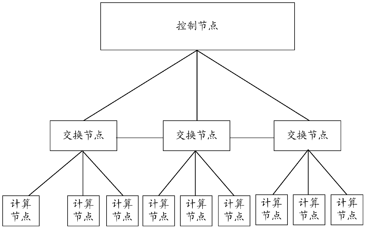
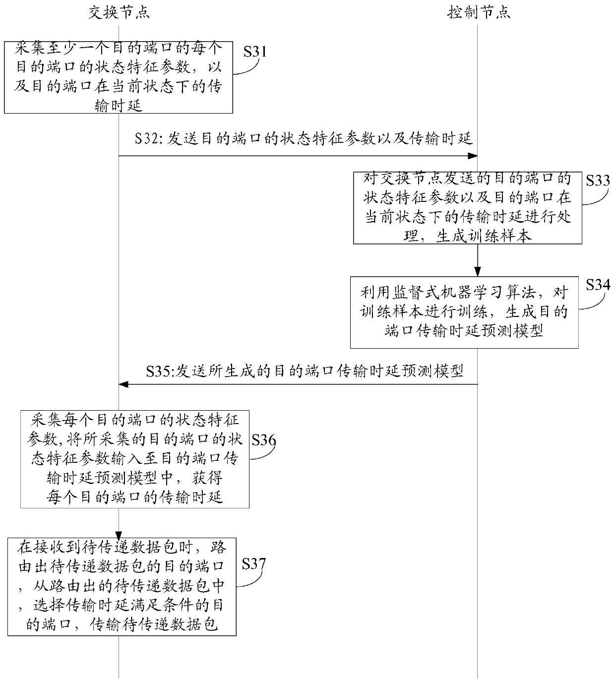
[0042] against figure 1 As shown in the network architecture where the control plane and the data plane are separated, the embodiment of the present invention provides a method for predicting the transmission delay of the destination port of the switching node, such as image 3 As shown, the method includes at least:

[0043] Step S31: the switching node collects the state characteristic parameters of each destination port in at least one destination port, and the transmission delay of the destination port in the current state;

[0044] In the embodiment of the present invention, each destination port state characteristic parameter may be at least one of the time interval for the destination port to receive reputation messages, the estimated busy time of the destination port, and the time the destination port is occupied by data packets;

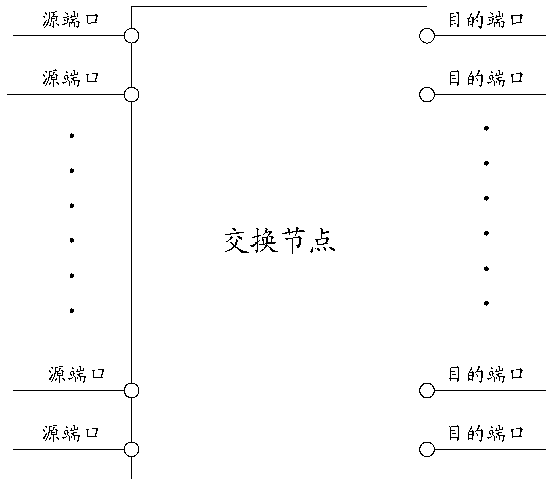
[0045] In the embodiment of the present invention, such as Figure 4 As shown, there are multiple virtual channels at the destination por...

Embodiment 2

[0059] In the embodiment of the present invention, in order to make the transmission delay prediction of the destination port more accurate, the transmission delay prediction model of the destination port can be updated periodically, and the specific method is as follows:

[0060] Since in practical applications, the switching node can obtain the actual transmission delay of the destination port in the corresponding state only when the data packet has been transferred, therefore, in the embodiment of the present invention, according to whether the destination port has transferred the data packet, specifically provide The following two ways to update the destination port transmission delay prediction model;

[0061] The first method: when the destination port has finished transmitting the data packet, the switch node obtains the actual transmission delay of the destination port; uploads the state characteristic parameters of the destination port and the actual transmission delay...

Embodiment 3

[0065] Corresponding to the aforementioned method embodiments, the present invention also provides a device for predicting the transmission delay of a destination port of a switching node, where the switching node includes a plurality of destination ports, such as Figure 6 As shown, the device at least includes:

[0066] The first receiving unit 61 is configured to receive the time interval and the transmission delay for each destination port in the at least one destination port to receive the reputation message, and the transmission delay of a destination port is the time interval for the destination port to receive the reputation message state, the time interval from when a data packet arrives at the destination port to when it is output from the destination port; the reputation message received by a destination port is sent by the next-hop switching node of the destination port to indicate the A message that the destination port sends a data packet to the corresponding nex...


PUM


Abstract

The invention discloses a method and device for predicting the transmission delay of a destination port in a switching node. The switching node comprises at least one destination port. The method comprises the following steps: a control node receives the time interval and the transmission delay that each destination port in the at least one destination port receives a credit message; according to the time interval and the transmission delay that each destination port in the at least one destination port receives the credit message, the control node updates an original destination port transmission delay predication model, and generates an updated destination port transmission delay predication model; and the control node sends the updated destination port transmission delay predication model to all switching nodes managed by the control node, so that each switching node in all the switching nodes managed by the control node can predict the transmission delay of each destination port in each switching node according to the updated destination port transmission delay predication model. By means of the method and the device disclosed by the invention, the network transmission rate can be increased.

Description

technical field [0001] The invention relates to the technical field of computer networks, in particular to a method and device for predicting the transmission time delay of a switching node destination port. Background technique [0002] With the rapid development of the Internet, the requirements for network transmission quality are getting higher and higher. Based on this, relevant technical personnel have proposed a network architecture in which the control plane and the data plane are separated; among them, as figure 1 As shown, the above-mentioned network architecture is mainly composed of three parts, which are control nodes, switching nodes, and computing nodes; among them, the control nodes can be specifically controllers for unified management of computing nodes and switching nodes; and switching nodes can be specifically It is a switch or a router, and is used to transfer business data between different computing nodes, and the computing nodes can be specifically p...

Claims


Application Information

Patent Timeline
Patent Type & Authority Patents(China)
IPC IPC(8): H04L12/26
Inventor 梁冬付斌章陈威屹
Owner INST OF COMPUTING TECH CHINESE ACAD OF SCI
Why Eureka
Eureka Blog
Learn More