Link aggregation transmission method and device, terminal and storage medium

A link aggregation and transmission method technology, applied in the field of communication, can solve problems such as easy loss of important business data, failure to meet low latency requirements, etc.

Inactive Publication Date: 2020-03-31
ZTE CORP
View PDF6 Cites 2 Cited by
  • Summary
  • Abstract
  • Description
  • Claims
  • Application Information

AI Technical Summary

Problems solved by technology

However, the existing LAG technology cannot meet the existing complex and diverse transmission requirements, it is easy to lose important business data, and cannot meet the low latency requirements

Method used


Image

  • Link aggregation transmission method and device, terminal and storage medium
  • Link aggregation transmission method and device, terminal and storage medium
  • Link aggregation transmission method and device, terminal and storage medium

Examples


Embodiment Construction

[0056]In order to make the purpose, technical solutions and advantages of the embodiments of the present invention more clear, the specific technical solutions of the invention will be further described in detail below in conjunction with the drawings in the embodiments of the present invention. The following examples are used to illustrate the present invention, but are not intended to limit the scope of the present invention.

[0057] It should be noted here that in this embodiment of the present invention, the terminal may be various microwave devices, and the transmission link may be a microwave link between two microwave devices.

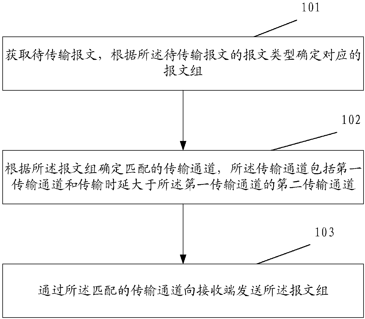
[0058] An embodiment of the present invention provides a link aggregation transmission method, which is applied to a sending end. The sending end may be the terminal as described above. Further, the sending end may be a microwave device. see figure 1 , the method includes the steps of:

[0059] Step 101, obtaining a message to be transmitted,...


PUM


Abstract

The embodiment of the invention discloses a link aggregation transmission method and device, a terminal and a computer storage medium, and the method comprises the steps: obtaining a to-be-transmittedmessage, and determining a corresponding message group according to the message type of the to-be-transmitted message; determining a matched transmission channel according to the message group, wherein the transmission channel comprises a first transmission channel and a second transmission channel of which the transmission delay is greater than that of the first transmission channel; and sendingthe message group to a receiving end through the matched transmission channel.

Description

technical field [0001] The present invention relates to communication technology, in particular to a link aggregation method, device, terminal and computer storage medium. Background technique [0002] With the continuous development of communication technology, the bandwidth of a microwave single link is difficult to meet the continuously increasing bandwidth requirements. Therefore, it is proposed to aggregate more than two microwave links and bundle them into a logical link, that is, a link aggregation group (LAG). , LinkAggregation Group). The LAG is applied at the physical layer to implement grouping at the physical layer, so that the traffic of each group is evenly shared, and the bandwidth of each microwave link is fully utilized. However, the existing LAG technology cannot meet the existing complex and diverse transmission requirements, is prone to loss of important business data, and cannot meet the low latency requirements. Contents of the invention [0003] In...

Claims


Application Information

Patent Timeline
Patent Type & Authority Applications(China)
IPC IPC(8): H04L12/709H04L12/24H04L12/865H04L12/877H04L45/243H04L47/525H04L47/6275
CPCH04L45/245H04L47/525H04L47/6275H04L41/0663H04L41/0803
Inventor 姚文达
Owner ZTE CORP
Why Eureka
Try Eureka