
A kind of led linear driver, driving circuit, chip and driving method

A technology of linear driver and clamping circuit, which is applied in the direction of electric light source, electrical components, electroluminescent light source, etc., can solve the problems of poor linear adjustment rate, low power conversion efficiency, narrow input voltage range, etc., and improve the linear adjustment rate Effect

Active Publication Date: 2019-03-12
SHANGHAI BRIGHT POWER SEMICONDUCTOR CO LTD
View PDF7 Cites 0 Cited by
  • Summary
  • Abstract
  • Description
  • Claims
  • Application Information

AI Technical Summary

Problems solved by technology

[0003] 1) Narrow input voltage range;
[0004] 2) Low power conversion efficiency;
[0005] 3) Poor linear adjustment rate

Method used


Image

  • A kind of led linear driver, driving circuit, chip and driving method
  • A kind of led linear driver, driving circuit, chip and driving method
  • A kind of led linear driver, driving circuit, chip and driving method

Examples


Embodiment Construction

[0076] Embodiments of the present invention are described below through specific examples, and those skilled in the art can easily understand other advantages and effects of the present invention from the content disclosed in this specification. The present invention can also be implemented or applied through other different specific implementation modes, and various modifications or changes can be made to the details in this specification based on different viewpoints and applications without departing from the spirit of the present invention. It should be noted that, in the case of no conflict, the following embodiments and features in the embodiments can be combined with each other.

[0077] It should be noted that the diagrams provided in the following embodiments are only schematically illustrating the basic ideas of the present invention, and only the components related to the present invention are shown in the diagrams rather than the number, shape and shape of the compo...


PUM


Abstract

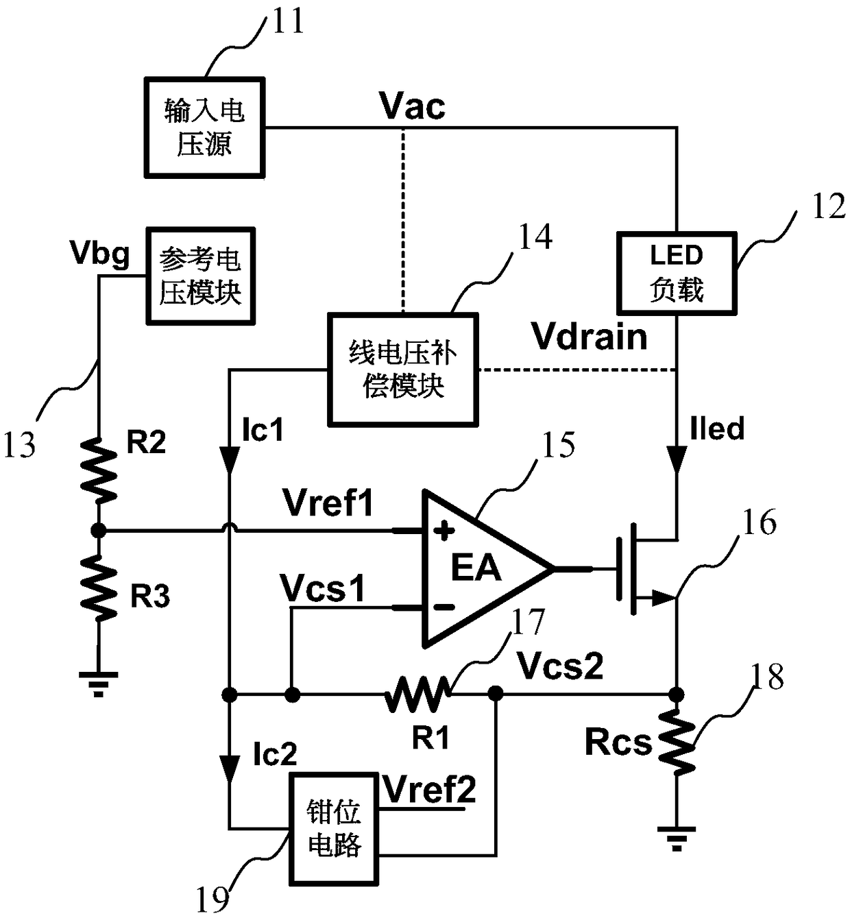
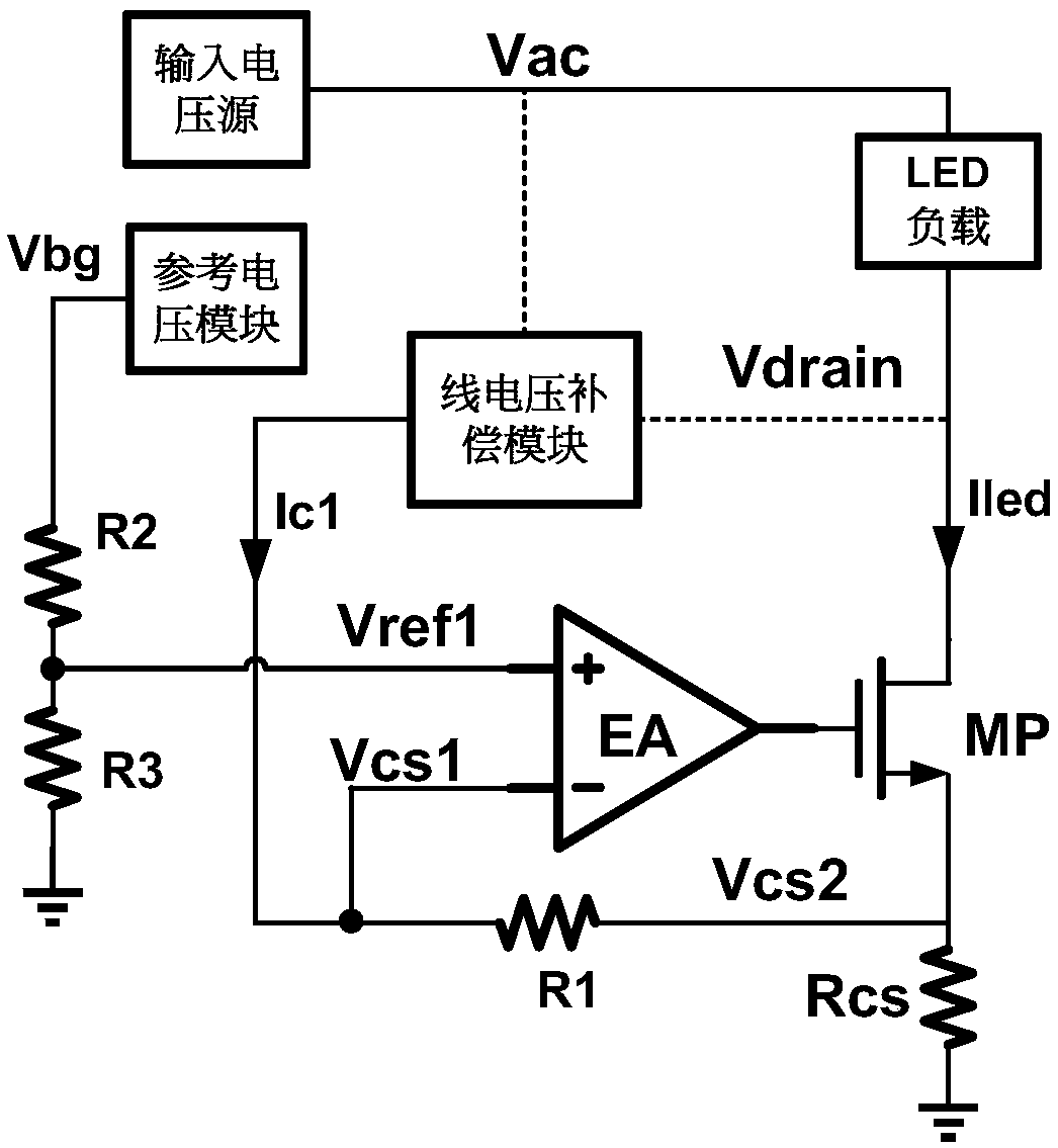
The invention provides an LED linear driver, a driving circuit, a chip and a driving method, including a line voltage compensation module and a clamping circuit; Compensation current in a proportional relationship; the first input end of the clamp circuit is used to access the second reference voltage, the second input end is used to sample the voltage at both ends of the current detection resistor electrically connected to the LED linear driver, and the output end is connected to the first The compensation resistor is connected; when the voltage across the current detection resistor is greater than the second reference voltage, the NMOS tube is turned off, and all the compensation current flows through the first compensation resistor; when the voltage across the current detection resistor is equal to the second reference voltage, part of the compensation current flows Through the first compensation resistor, the voltage valley on the current detection resistor is clamped at the second reference voltage. The LED linear driver, the driving circuit, the chip and the driving method of the invention improve the linear adjustment rate of the LED linear driver.

Description

technical field [0001] The invention relates to the technical field of electronic circuits, in particular to an LED linear driver, a driving circuit, a chip and a driving method. Background technique [0002] Compared with the switching driver, due to its obvious advantages such as low cost, no EMI interference, no noise in dimming, and easy photoelectric integration, linear drivers driving LEDs are developing rapidly with their unique advantages. However, linear drives also have the following unavoidable disadvantages: [0003] 1) Narrow input voltage range; [0004] 2) Low power conversion efficiency; [0005] 3) Poor linear adjustment rate. [0006] In the prior art, more and more technologies are devoted to improving the above shortcomings of the linear driver. In particular, the linear adjustment rate is a very important index, so it is very necessary to improve the linear adjustment rate of the output of the LED linear constant current driver. Contents of the inv...

Claims


Application Information

Patent Timeline
Patent Type & Authority Patents(China)
IPC IPC(8): H05B33/08H05B44/00
CPCH05B45/395
Inventor 郑儒富
Owner SHANGHAI BRIGHT POWER SEMICONDUCTOR CO LTD
Learn More