
Laser welding fixture

A fixing device and laser welding technology, applied in the field of laser welding, can solve the problem of inability to adjust the welding workpiece and the incidence angle of laser welding, and achieve the effect of improving welding quality

Inactive Publication Date: 2017-03-22
CRRC QINGDAO SIFANG CO LTD
View PDF13 Cites 1 Cited by
  • Summary
  • Abstract
  • Description
  • Claims
  • Application Information

AI Technical Summary

Problems solved by technology

[0006] The invention provides a laser welding fixture to solve the problem in the prior art that the angle of incidence between the welding workpiece and the laser welding cannot be adjusted

Method used


Image

  • Laser welding fixture

Examples


Embodiment Construction

[0022] The following will clearly and completely describe the technical solutions in the embodiments of the present invention with reference to the accompanying drawings in the embodiments of the present invention. Obviously, the described embodiments are only some, not all, embodiments of the present invention. The following description of at least one exemplary embodiment is merely illustrative in nature and in no way taken as limiting the invention, its application or uses. Based on the embodiments of the present invention, all other embodiments obtained by persons of ordinary skill in the art without creative efforts fall within the protection scope of the present invention.

[0023] It should be noted that the terminology used here is only for describing specific implementations, and is not intended to limit the exemplary implementations according to the present application. As used herein, unless the context clearly dictates otherwise, the singular is intended to include...


PUM


Abstract

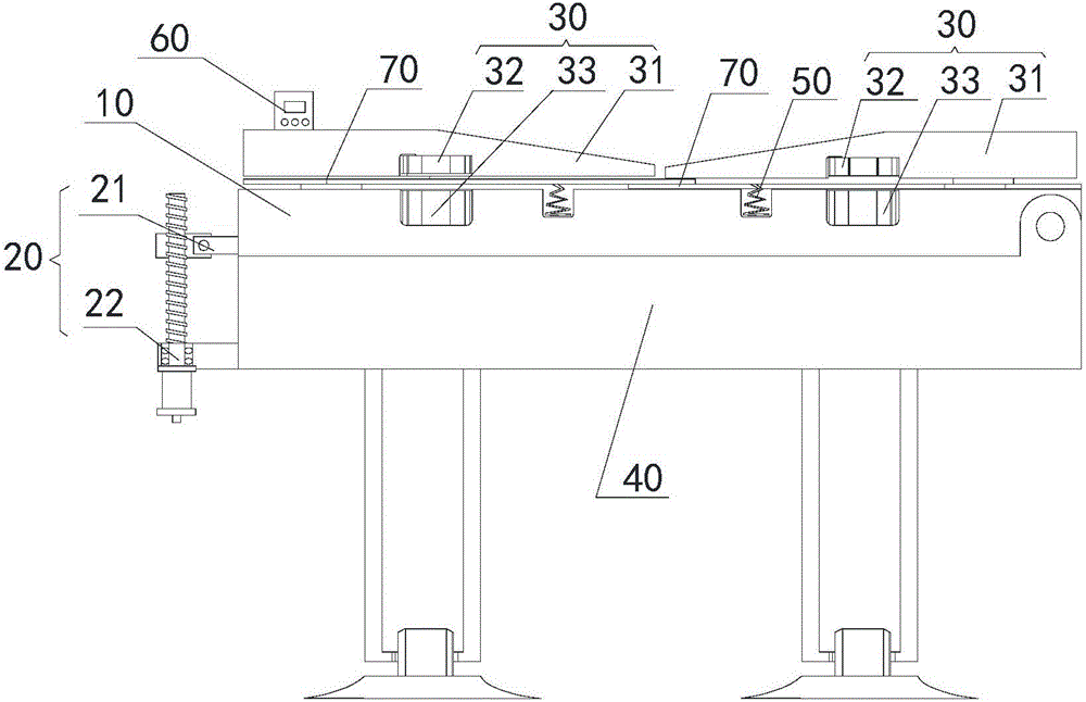
The invention provides a laser welding fixture. The laser welding fixture comprises a bottom plate, a driving device and a clamping device, wherein the bottom plate is used for placing workpieces; the driving device is in driving connection with the bottom plate and is used for adjusting an included angle between the bottom plate and a first direction; the clamping device is arranged on the bottom plate and is used for fixing positions of the workpieces in the bottom plate. Through the technical scheme, the problem that the incident angle between the welded workpieces and the laser welding cannot be adjusted in the prior art can be solved.

Description

technical field [0001] The invention relates to the technical field of laser welding, in particular to a laser welding fixing device. Background technique [0002] At present, in the field of rail transit, based on various advantages of laser welding, laser lap welding technology is gradually replacing spot welding technology. [0003] Patent No. CN 104942454A provides a laser welding construction device, which uses the magnetic force generated by the electro-permanent magnetic field to clamp stainless steel, which eliminates the gap between the workpieces and ensures the tight fit between the workpieces. The invention can realize the close bonding of workpieces, but the incident angle of the laser beam cannot be adjusted when the laser beam is fixed. [0004] Patent No. CN 105499867A provides a thin-plate laser welding fixture, which is provided with a substrate box on the base, and a Y-direction sliding fastening plate that is slidably matched with the substrate box is pr...

Claims


Application Information

Patent Timeline
Patent Type & Authority Applications(China)
IPC IPC(8): B23K26/70B23K37/047
CPCB23K26/702B23K37/047
Inventor 韩晓辉赵瑞荣方喜风陶传琦郑凯
Owner CRRC QINGDAO SIFANG CO LTD
Learn More