Clamp of overflow plate

An over-current and fixture technology, applied in the direction of clamping, manufacturing tools, supports, etc., can solve the problems of low efficiency, cumbersome clamping, complex structure, etc., and achieve the effect of easy operation, reducing positioning interference, and improving clamping efficiency.

Inactive Publication Date: 2017-03-22
WUXI KAIHAN TECH
View PDF8 Cites 1 Cited by
  • Summary
  • Abstract
  • Description
  • Claims
  • Application Information

AI Technical Summary

Problems solved by technology

[0003] In view of the above problems, the present invention provides a clamp for the overflow plate, which can solve the technical problems of the existing clamp structure for the overflow plate, cumbersome clamping, and low efficiency

Method used


Image

  • Clamp of overflow plate
  • Clamp of overflow plate
  • Clamp of overflow plate

Examples


Embodiment Construction

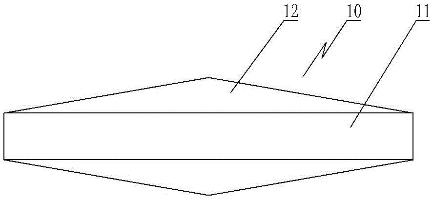
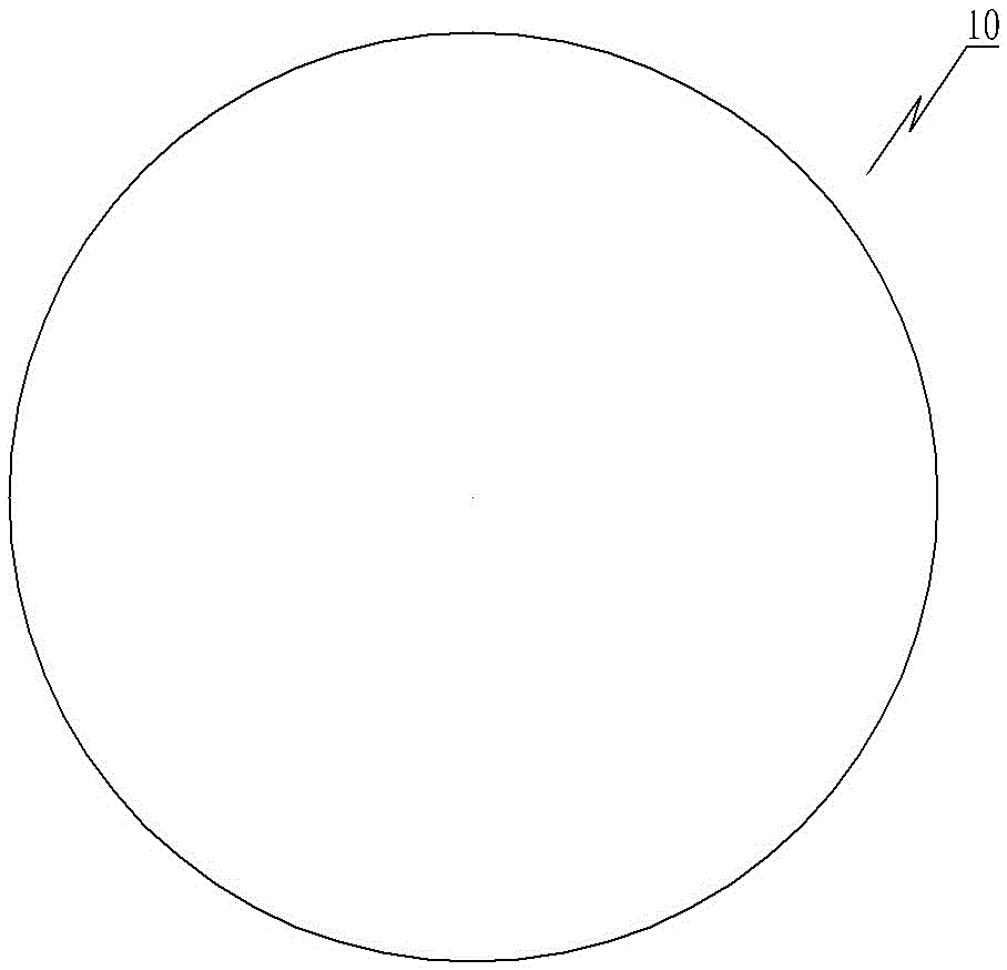
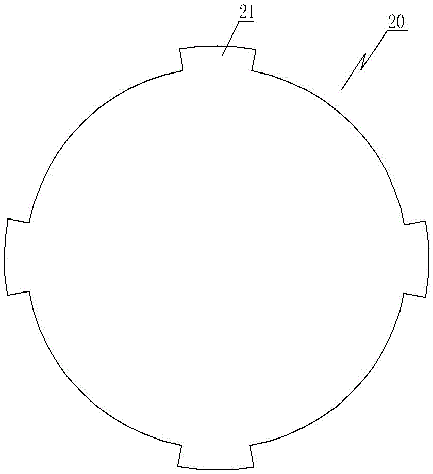
[0022] Such as Figure 1 to Figure 7 As shown, the clamp 30 of the overflow plate includes a movable clamp block 31, a fixed clamp block 32, and a pressing mechanism for pressing the movable clamp block 31 to be fixed on the fixed clamp block 32; the movable clamp block 31 is provided with The first positioning groove, the first positioning groove includes the first upper groove body 311, the first middle groove body 312 and the first lower groove body 313 connected to each other; the fixed clip 32 is provided with the second positioning groove, the second positioning groove It includes a second upper tank body 321, a second middle tank body 322 and a second lower tank body 323 connected to each other; the first upper tank body 311 is a V-shaped groove, and the inner side walls of the tank body 3111, 3112 of the first upper tank body 311 , 3113 are respectively tangent to the side of the columnar main body of the semi-finished product, the second middle tank body 322 is an arc...


PUM


Abstract

The invention provides a clamp of an overflow plate, and the clamp can be used for solving the technical problem of complex structure, clamping trouble and low efficiency of the existing clamp of the overflow plate. The clamp comprises a movable clamping block, a fixed clamping block and a pressing mechanism used for press-fitting and fixing the movable clamping block on the fixed clamping block; a first locating slot is formed in the movable clamping block and comprises a first upper slot body and a first middle slot body which are connected with each other; a second locating slot is formed in the fixed clamping block and comprises a second upper slot body and a second middle slot body which are connected with each other; the first upper slot body is a V-shaped slot, the inner side wall of each of the slot bodies of the first upper slot body is tangent with the side of a columnar main body of a semi-finished product, the second middle slot body is an arc-shaped slot and is matched with the columnar main body of the semi-finished product of the overflow plate, and the central angle corresponding to the second upper slot body is larger than 180 DEG; and the first middle slot body and the second middle slot body are spliced to form a conical locating slot matched with a conical part of the semi-finished product of the overflow plate.

Description

technical field [0001] The invention relates to the field of processing parts of textile equipment, in particular to a clamp for a flow plate. Background technique [0002] A flow plate for textile equipment, its finished product 20 such as image 3 As shown semi-finished products 10 such as Figure 1~Figure 2 shown. The semi-finished product 10 of the overflow plate includes a columnar body 11 and the tapered parts 12 symmetrically arranged at both ends of the columnar body in the axial direction; the finished product 20 of the overflow plate is processed on the basis of the semi-finished product. The thickness is smaller than that of the columnar body 11 . Existing fixtures usually simultaneously position and press-fit the tapered parts at both ends, and expose the radially outer peripheral parts of the columnar body that need to be processed. The fixture has a complex structure, cumbersome clamping, and low efficiency. Contents of the invention [0003] In view of th...

Claims


Application Information

Patent Timeline
Patent Type & Authority Applications(China)
IPC IPC(8): B23Q3/06
CPCB23Q3/062
Inventor 姚舜雄
Owner WUXI KAIHAN TECH
Why Eureka
Try Eureka