Work fixture for transition plate

A tooling fixture and overcurrent technology, applied in the direction of manufacturing tools, clamping, positioning devices, etc., can solve the problems of cumbersome clamping, complex structure, low efficiency, etc., to reduce positioning interference, improve clamping efficiency, and easy to operate. Effect

Inactive Publication Date: 2017-05-17
WUXI KAIHAN TECH
View PDF7 Cites 0 Cited by
  • Summary
  • Abstract
  • Description
  • Claims
  • Application Information

AI Technical Summary

Problems solved by technology

[0003] In view of the above problems, the present invention provides a tooling fixture for the overflow plate, which can solve the technical problems of the existing tooling fixture for the overflow plate with complex structure, cumbersome clamping, and low efficiency

Method used


Image

  • Work fixture for transition plate
  • Work fixture for transition plate
  • Work fixture for transition plate

Examples


Embodiment Construction

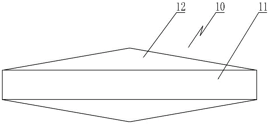
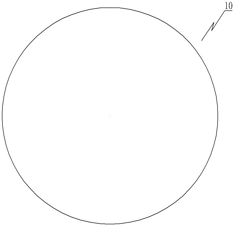
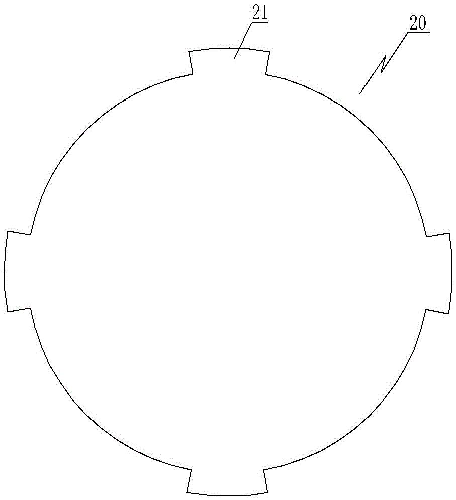
[0021] Such as Figure 1 to Figure 6 As shown, the fixture 30 of the flow plate includes a movable clamp block 31, a fixed clamp block 32, and a pressing mechanism for press-fitting and fixing the movable clamp block 31 on the fixed clamp block 32; the movable clamp block 31 is provided with There is a first positioning groove. The first positioning groove includes a first upper groove body 311, a first middle groove body 312 and a first lower groove body 313 that are connected to each other; a second positioning groove is provided on the fixing clamp block 32, and the second positioning groove The groove includes a second upper groove body 321, a second middle groove body 322 and a second lower groove body 323 which are connected to each other; the first upper groove body 311 and the second middle groove body 322 are combined to form a semi-finished cylindrical body with the flow plate Matching cylindrical positioning grooves, the first middle groove body 312 and the second mi...


PUM


Abstract

The invention provides a work fixture for a transition plate. The technical problem that existing work fixtures for transition plates are complex in structure, tedious in clamping and low in efficiency can be solved. The work fixture comprises a movable fixture block, a fixed fixture block and a hold-down mechanism used for pressing and fixing the movable fixture block to the fixed fixture block. A first positioning groove is formed in the movable fixture block and comprises a first upper groove body and a first intermediate groove body connected with the first upper groove body. A second positioning groove is formed in the fixed fixture block and comprises a second upper groove body and a second intermediate groove body connected with the second upper groove body. A columnar positioning groove matched with a semi-finished columnar main body of the transition plate is formed by splicing the first upper groove body and the second intermediate groove body. A conical positioning groove matched with a semi-finished conical part of the transition plate is formed by splicing the first intermediate groove body and the second intermediate groove body. The central angle of the second upper groove body is larger than 180 degrees.

Description

Technical field [0001] The invention relates to the processing field of parts and components of textile equipment, in particular to a tooling fixture for an overflow plate. Background technique [0002] A kind of flow plate, used in textile equipment, the finished product 20 such as image 3 As shown in semi-finished products 10 Figure 1~Figure 2 Shown. The semi-finished product 10 of the flow plate includes a cylindrical body 11 and tapered parts 12 symmetrically arranged at the axial ends of the cylindrical body; the finished product 20 of the flow plate is processed with positioning protrusions 21 on the basis of the semi-finished product. The thickness is smaller than the thickness of the columnar body 11. The existing tooling fixture usually simultaneously locates and press-fits the tapered parts at both ends, and exposes the radial outer peripheral part of the cylindrical body that needs to be processed. The tooling fixture has a complex structure, cumbersome clamping and ...

Claims


Application Information

Patent Timeline
Patent Type & Authority Applications(China)
IPC IPC(8): B23Q3/06
CPCB23Q3/06B23Q3/062
Inventor 姚舜雄
Owner WUXI KAIHAN TECH
Why Eureka
Try Eureka