Clamp device for processing brake cylinder of high-speed rail train

A fixture device and brake technology, applied in positioning devices, manufacturing tools, metal processing equipment, etc., can solve the problems of high cost, high processing cost, low efficiency, etc., and achieve the effect of improving efficiency, reducing cost and improving product qualification rate

Inactive Publication Date: 2011-08-17
NINGBO YONGXIN AUTO COMPONENTS MFG
View PDF5 Cites 21 Cited by
  • Summary
  • Abstract
  • Description
  • Claims
  • Application Information

AI Technical Summary

Problems solved by technology

[0002] The high-speed rail brake cylinder is a component of the high-speed railway train brake. During production, it needs to perform drilling, boring and milling comprehensive cutting processing on its multiple surfaces. In order to ensure the mutual shape and position tolerance of each processing surface, it is required to complete multiple surfaces in one clamping. Processing, the existing technology uses a large horizontal five-axis machining center to cut the cylinder block of the high-speed rail brake. The large horizontal five-axis machining center is an expensive and general-purpose metal cutting processing equipment, and its processing cost is also high. The center processes high-speed rail brake cylinders in large quantities, which makes the cost of high-speed rail brake cylinders high;
[0003] Using ordinary three-axis machining centers to process high-speed rail brake cylinders requires multiple surface changes and clamping processes, and the accumulation of deviations in multiple clamping and surface changes leads to the problem that the shape and position tolerance of the product is easily out of tolerance and the processing efficiency is low; Therefore, the prior art has the problems and deficiencies of high cost, low efficiency, and easy out-of-tolerance defects

Method used


Image

  • Clamp device for processing brake cylinder of high-speed rail train
  • Clamp device for processing brake cylinder of high-speed rail train

Examples


Embodiment Construction

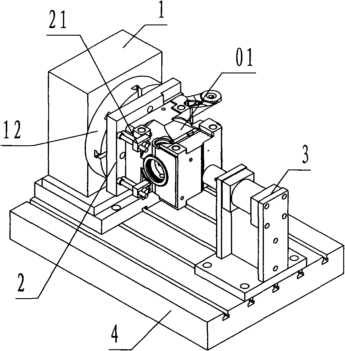
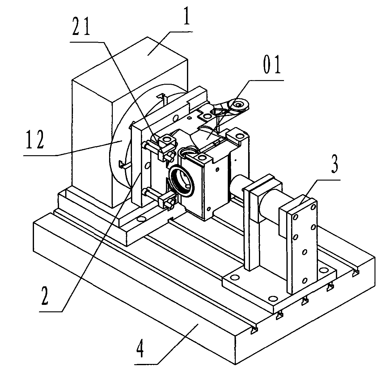
[0016] refer to figure 1 , a fixture device for processing high-speed rail brake cylinders according to the present invention includes an indexing head 1, a positioning fixture 2, a cylinder tail top 3, and a pedestal 4, wherein: the indexing head 1 is driven by a hydraulic valve and controlled For the quartering rotary indexing device of the controller of the CNC milling machine, the output end of the indexing head 1 is provided with an indexing head chuck 12;

[0017] The positioning fixture 2 is a device for clamping the workpiece 01 made of a rectangular steel plate. The back side of the positioning fixture 2 is a plane that cooperates with the indexing head chuck 12. The profiled surface and positioning pins and positioning holes, the periphery of the profiled surface is provided with a number of jaws 21 composed of bolts and pressure plates;

[0018] The tail top 3 of the cylinder is a device that fixes a pneumatic cylinder on a steel support, the cylinder body of the c...


PUM


Abstract

The invention discloses a clamp device for processing a brake cylinder of a high-speed rail train, comprising a dividing head (1), a positioning clamp (2), a cylinder tail stock (3) and a pedestal. In the technical scheme, the clamp device is formed by the quarter dividing head driven and locked by a high-accuracy hydraulic valve, the positioning clamp, the cylinder tail stock and the pedestal; when in application, the positioning clamp is clamped by a dividing head clamping disc; a workpiece is clamped by the positioning clamp and is tightly pressed on the positioning clamp by means of the cylinder tail stock; and the hydraulic valve of the dividing head is driven by a numerical control milling machine to control the dividing head to drive the workpiece to be matched with the cutting of a cutting tool in a controlled mode so as to automatically rotate and change the surface. Thus, the invention overcomes the problems and defects of high cost, low efficiency and possible out-of-tolerance in the prior art, and ensures that the multi-surface processing of the brake cylinder of the high-speed rail train can be finished in one-time clamping procedure on a general numerical control milling machine through fast clamping and controlled rotation and surface changing, thereby achieving the purposes of reducing the cost, improving the efficiency and improving the product qualification rate.

Description

technical field [0001] The invention relates to a cutting process device, in particular to a fixture device for machining a cylinder block of a high-speed rail brake for drilling, boring and milling on a numerically controlled milling machine. Background technique [0002] The high-speed rail brake cylinder is a component of the high-speed railway train brake. During production, it needs to perform drilling, boring and milling comprehensive cutting processing on its multiple surfaces. In order to ensure the mutual shape and position tolerance of each processing surface, it is required to complete multiple surfaces in one clamping. Processing, the existing technology uses a large horizontal five-axis machining center to cut the cylinder block of the high-speed rail brake. The large horizontal five-axis machining center is an expensive and general-purpose metal cutting processing equipment, and its processing cost is also high. The center processes high-speed rail brake cylind...

Claims


Application Information

Patent Timeline
Patent Type & Authority Applications(China)
IPC IPC(8): B23Q3/06B23Q16/02
Inventor 娄荣校王昌武
Owner NINGBO YONGXIN AUTO COMPONENTS MFG
Why Eureka
Try Eureka