Clamping device for adjoining board materials

a technology of clamping device and adjoining board, which is applied in the direction of clamps, manufacturing tools, and surfaces, can solve the problems of hardly quick clamping of slates and still quite time-consuming processes

Inactive Publication Date: 2012-12-04
GISON MASCH CO LTD
View PDF5 Cites 20 Cited by
  • Summary
  • Abstract
  • Description
  • Claims
  • Application Information

AI Technical Summary

Benefits of technology

[0010]It is therefore a primary object of the present invention to provide a clamping device, which is able to quickly clamp a horizontal board material and an upright board material for adjoining the board materials and release the board materials after adjoined.
[0011]It is a further object of the present invention to provide the above clamping device, which includes a horizontal holder mechanism. The horizontal holder mechanism serves to adjustably abut against the upright board material at a suitable height so as to more securely hold the upright board material.

Problems solved by technology

First, the cantilever 26 of the clamping device 10 serves to enhance the stability of the upright slate 16. However, the cantilever 26 simply contacts with the top edge of the slate without supporting the slate in any other position.
Second, when clamping the slate, the engaging plate 23 is engaged in a most suitable annular groove 191 of the outer tube 19 of the clamping rod 17 to space the clamp head 22 from the horizontal slate 14 by a shortest gap. Then the threaded rod 20 is rotated to lower the clamp head 22 for clamping the slate 14. The second clamping rod 18 is operated in the same manner. Such process is still quite time-consuming so that the slates can be hardly quickly clamped.

Method used


Image

  • Clamping device for adjoining board materials
  • Clamping device for adjoining board materials
  • Clamping device for adjoining board materials

Examples


Embodiment Construction

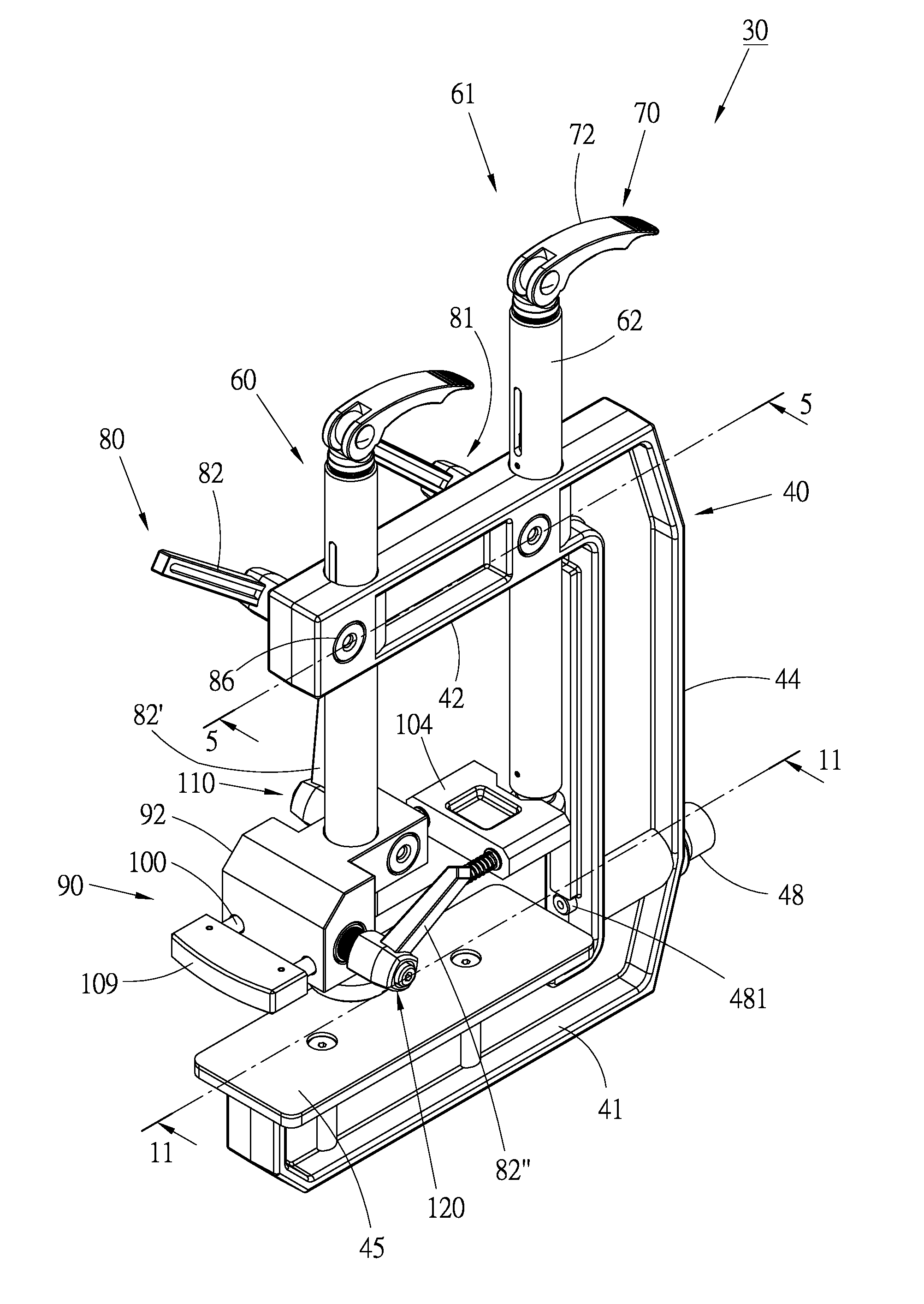
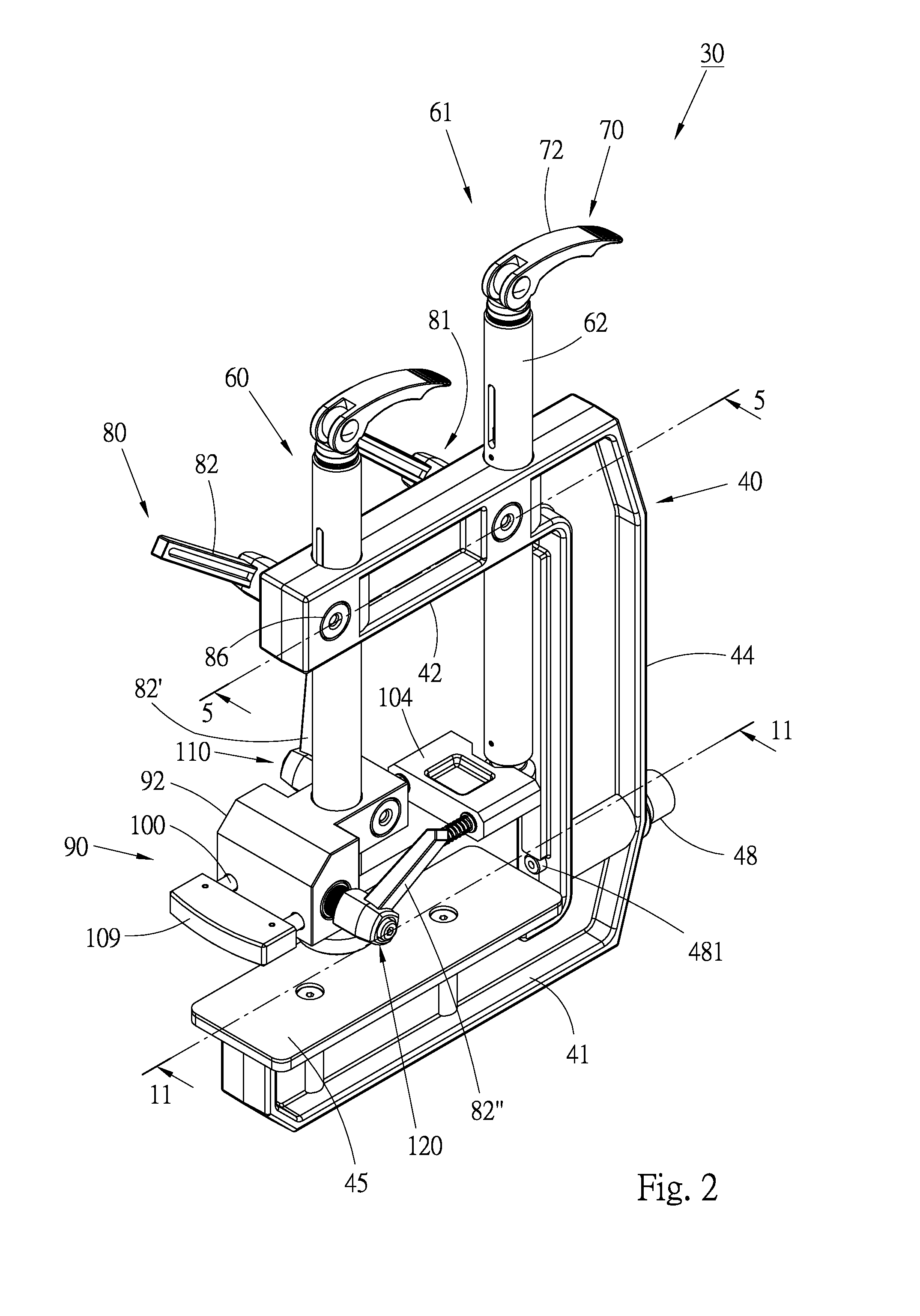
[0027]Please refer to FIGS. 2 to 4. According to a preferred embodiment, the clamping device 30 of the present invention is used to clamp board materials such as slates or wooden boards. The clamping device 30 includes a base 40, a first press rod 60, a second press rod 61, two first fastener assemblies 80, 81, a horizontal holder mechanism 90, and a second fastener assembly 110 and a third fastener assembly 120 mounted on the horizontal holder mechanism 90.

[0028]The base 40 is C-shaped, having a horizontal base section 41, a top arm 42 and an upright arm 44 connected between the base section 41 and the top arm 42. The base section 41, the top arm 42 and the upright arm 44 define therebetween a space for resting board materials therein. A bottom board 45 is mounted to a top face of the base section 41 by means of threaded members 451 for enlarging contact area between the base 40 and a horizontal board material. A vertical standard face 46 is disposed on an inner side of the upright...


PUM


Abstract

A clamping device for adjoining board materials includes: a C-shaped base having a base section, a top arm and an upright arm; a first press rod and a second press rod vertically movably fitted through the top arm; two first fastener assemblies for fastening and locating the press rods; a horizontal holder mechanism fitted on the first press rod and vertically movable along the first press rod; and a second fastener assembly for adjustably fastening the holder mechanism to the first press rod at a height. The holder mechanism includes at least one horizontally movable guide pin and an abutment member disposed at a front end of the guide pin. In use, a horizontal board material and an upright board material are placed in the base and fixedly held with the first and second press rods respectively. The abutment member serves to abut against and hold the upright board material.

Description

BACKGROUND OF THE INVENTION[0001]1. Field of the Invention[0002]The present invention relates generally to a mechanical apparatus, and more particularly to a clamping device for clamping board materials.[0003]2. Description of the Related Art[0004]In the manufacturing of products of stone materials, it is often necessary to adjoin two slates by an angle of 90 degrees. An adhesive is first applied to the junctures of the board materials and then the board materials are clamped and fixed with a clamping device. After the adhesive is hardened, the board materials are fixedly adjoined with each other.[0005]Conventionally, the slates are clamped by means of a C-shaped clamp. FIG. 1 shows a commercially available clamping device 10. The clamping device 10 has a base 12 for resting a horizontal slate 14 and an upright slate 16 thereon. The clamping device 10 further has a first clamping rod 17 and a second clamping rod 18, which are identically to each other in structure. The first and sec...

Claims


Application Information

Patent Timeline
Patent Type & Authority Patents(United States)
IPC IPC(8): B25B1/00B25B1/20B25B5/00B25B1/10B25B1/02
CPCB25B5/003B25B5/067B25B5/082B25B5/142
Inventor LIN, FREDDY
Owner GISON MASCH CO LTD
Why Eureka
Try Eureka