Mixing machine

A technology for mixers and motors, which is used in mixers, mixers with rotating containers, mixer accessories, etc., can solve problems such as irregular component wear, geometric deviation, and large wear

Active Publication Date: 2006-05-10
STARDALE
View PDF1 Cites 21 Cited by
  • Summary
  • Abstract
  • Description
  • Claims
  • Application Information

AI Technical Summary

Problems solved by technology

[0004] Another disadvantage of this known hybrid machine is that due to the use of two electric motors, and the associated belts and pulleys, this requires greater attention to the geometrical deviations of the machine assembly, especially the positioning of the belts, since possible mispositioning will result in Loud noise and irregular component wear that can cause belts to run out of the way they run
Also, the use of two electric motors requires additional electronic components, thus involving expensive overall outlays and considerable wear and tear

Method used


Image

  • Mixing machine
  • Mixing machine

Examples


Embodiment Construction

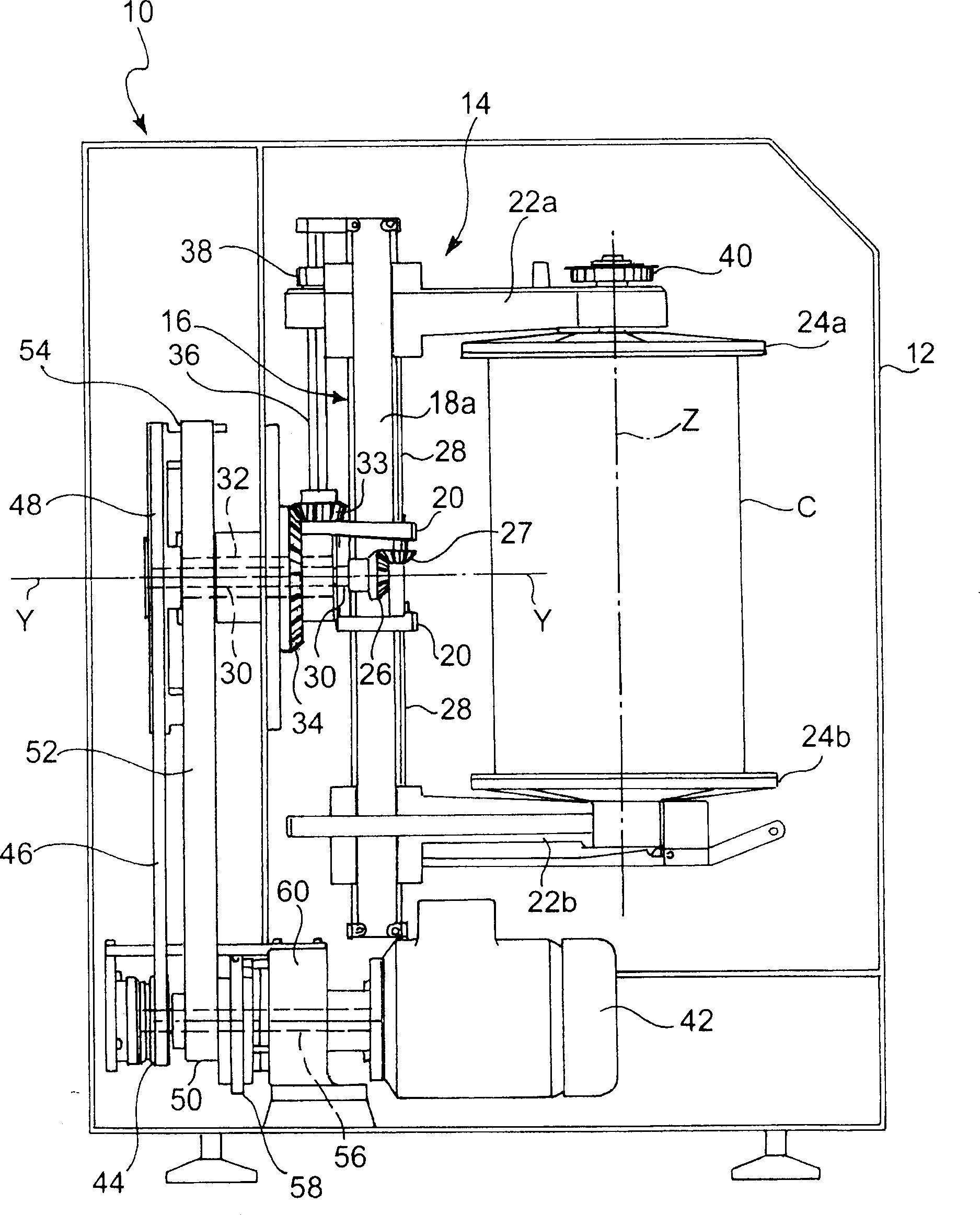
[0019] First refer to figure 1 , a mixer for mixing varnishes, paints, powdered products, seeds, etc. is indicated generally at 10 and comprises a frame 12 which accommodates and supports a container or tank C arranged to grip the product to be mixed and to make the The mechanism by which a container or tank rotates both about its longitudinal axis Z (vertical axis) and about a second axis Y (horizontal axis) perpendicular to the first axis.

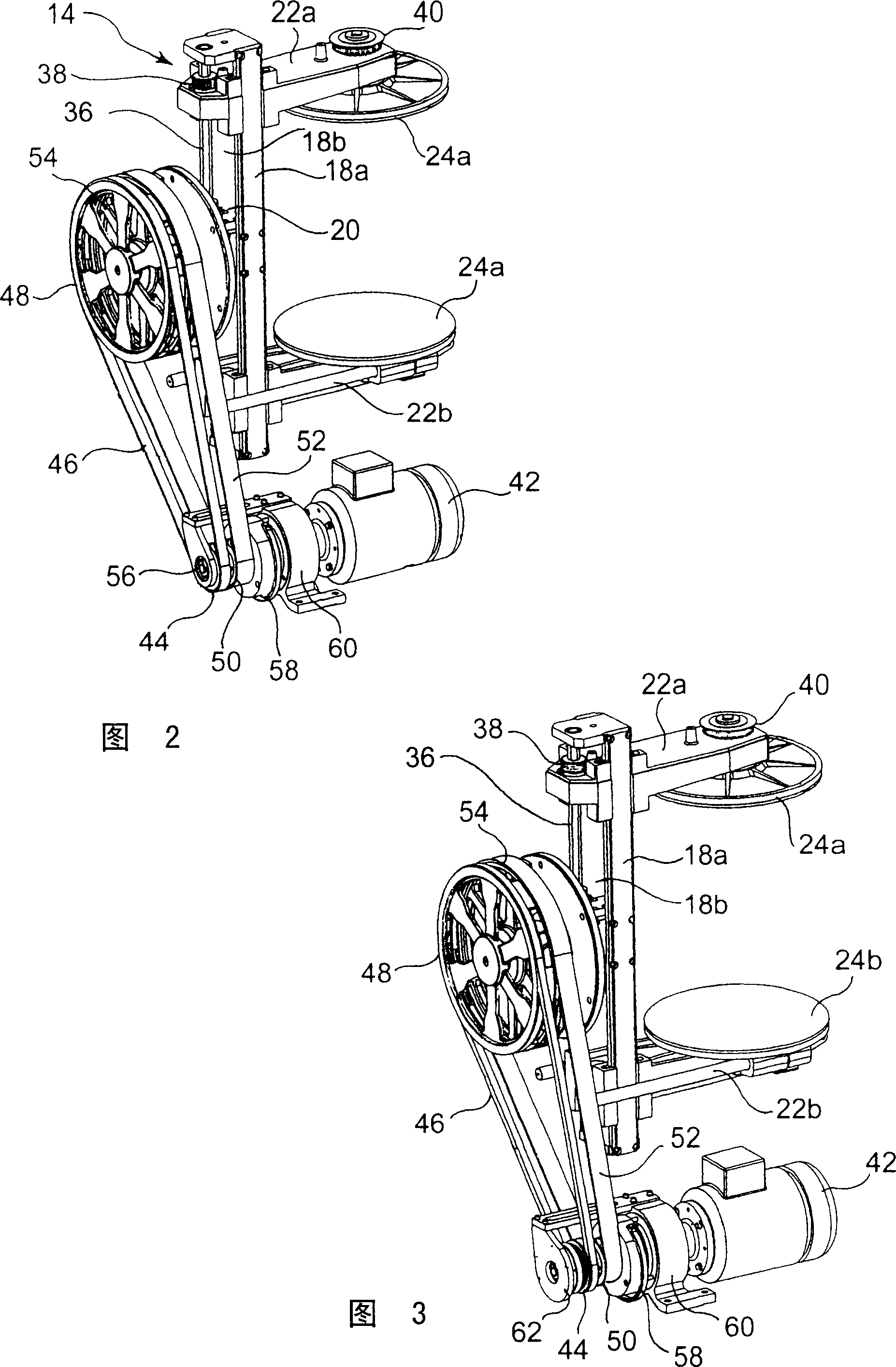
[0020] These mechanisms consist first of all of a clamping structure, shown generally at 14, supported by a frame 12 for rotation about a horizontal axis Y. The clamping structure 14 includes a swivel arm 16 comprising a pair of straight guide rods 18a, 18b (more clearly seen in FIGS. They are arranged in parallel and fixed centrally to the fork hub 20 . A pair of support members 22a, 22b with clamping plates 24a, 24b, respectively, are slidably fitted on two straight guide rods 18a, 18b, on opposite sides with respect to the Y axis, i...


PUM


Abstract

The invention relates to a clamping structure (14), which comprises a couple of clamping plates (24a, 24b) which can rotate around first axis (Z) and move oppositely, to clamp the container or pot (c) with mixed product at longitudinal opposite side. The clamping structure (14) is designed to rotate around the first axis (Z) and second axis (Y) to make the container or pot (C) synchronously rotate around said two axis (X, Y) vertical to each other. The inner drive axis (30) controls the clamping motion of clamping plates (24a, 24b), and the outer drive axis (32) controls the rotation of container or pot (C) around the axis (Y, Z) which are vertical to each other. And a motor (42) can via belt transmission gears (44, 46, 48, 50, 52, and 54) control the inner and outer drive axis (30, 32).

Description

technical field [0001] The present invention relates to a mixer for kneading or mixing liquid, solid or powder products such as especially varnishes, paints and the like. [0002] More particularly, the present invention relates to a gyroscopic mixer in which a tank, drum or other container containing a product is rotated both about its own longitudinal axis (vertical direction) and about its own axis (vertical direction) Horizontal direction) shaft rotation for product mixing mixer. Background technique [0003] EP-A-0955081 discloses a mixer of the above type comprising an inner drive shaft controlled by a first electric motor via a first belt and a first pulley; and an outer drive shaft which Coaxial with the first, controlled by a second motor via a second belt and a second pulley. The inner drive shaft controls the movement of a pair of upper and lower plates for clamping the container; while the outer drive shaft controls the rotation of the two upper clamping plates...

Claims


Application Information

Patent Timeline
Patent Type & Authority Applications(China)
IPC IPC(8): B01F9/00
CPCB01F29/10B01F35/423
Inventor G·M·布雷斯萨尼S·C·钦
Owner STARDALE
Why Eureka
Try Eureka