Eureka AIR delivers breakthrough ideas for toughest innovation challenges, trusted by R&D personnel around the world.

A high-precision rigid height and angle adjustment device

An angle adjustment device, high-precision technology, applied in the direction of building types, buildings, building components, etc., can solve problems such as insufficient horizontal and vertical stiffness, device deformation, and impact on the performance of shock-isolation bearings to achieve high stiffness and avoid interference , the effect of large height adjustment range

Active Publication Date: 2022-03-25
TONGJI UNIV
View PDF0 Cites 0 Cited by
  • Summary
  • Abstract
  • Description
  • Claims
  • Application Information

AI Technical Summary

Problems solved by technology

This adjustment method has three main disadvantages: (1) The horizontal position of the isolation support will change during the process of sliding the upper wedge-shaped slider to raise the height of the device, forcing the isolation support to produce shear deformation; (2) ) The traditional device is composed of upper and lower wedges, which mainly rely on the friction between the wedges to resist relative deformation, and the horizontal and vertical stiffness is insufficient, so that the device will undergo large deformation under the action of earthquakes, which will affect the performance of the isolation bearing; (3 ) The traditional device can only adjust the height of the support, but cannot adjust the out-of-plane corner of the support

Method used


Image

  • A high-precision rigid height and angle adjustment device
  • A high-precision rigid height and angle adjustment device
  • A high-precision rigid height and angle adjustment device

Examples


Embodiment

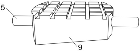
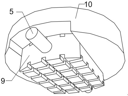
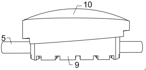
[0030] Example 1: The high-precision rigid height and angle adjustment device as shown in the figure, including the lower seat plate 1, the lower slider 9, the upper slider 10, the upper seat plate 2, the adjustable length bolts 3, the threaded holes 8, the upper seat plate Threaded countersunk hole 11, upper seat plate limit bolt 4, upper slider limit bolt 6, lower slider limit bolt 7 and long screw 5. The lower seat plate 1 is composed of two parts: a square steel plate and a thick-walled steel pipe. The square steel plate of the lower seat plate 1 is provided with four threaded holes 8 for connecting the rigid ground. From bottom to top, the thick-walled steel pipes of the lower seat plate 1 are respectively connected with the lower slider 9 , the upper slider 10 , and the upper seat plate 2 . The bottom surface of the lower slider 9 is flat, the top surface is an inclined surface, and oil grooves are opened on the bottom surface and the top surface to prevent foreign obje...


PUM


Abstract

The invention relates to a high-precision rigid height and angle adjustment device, which comprises a lower seat plate, a lower slider, an upper slider and an upper seat plate. The bottom surface of the lower slider is flat, the top surface is an inclined surface, and there are oil grooves on both the bottom surface and the top surface. The lower slider is located in the thick-walled steel pipe of the lower seat plate and stacked on the square steel plate of the lower seat plate. There is an inner concave inclined chute matching the top surface of the lower slider, and the upper slider and the thick-walled steel pipe of the lower seat plate are fixed by limit bolts. The bottom surface of the upper seat plate is provided with an inner concave spherical surface matching the outer convex spherical surface on the top surface of the upper slider, and an oil groove is opened. The upper seat plate is connected with the thick-walled steel pipe of the lower seat plate through limit bolts. This device can not only realize the high-precision stepless adjustment of height and angle, but also has the function of tensile resistance and high rigidity, so as to avoid the adjustment device from affecting the dynamic force of the upper structure. Response under load has an effect. This unit can be used for equipment mounts, isolator mount mounts, and where fine and rigid adjustable interfaces are required.

Description

technical field [0001] The invention relates to a high-precision rigid height and angle adjusting device, which belongs to the technical field of testing. Background technique [0002] During the installation of the seismic isolation supports of the seismic isolation structure, the supports at the bottom of the same building or structure should be located in the same horizontal plane. Inclinations may occur with individual bearing mounting surfaces. At this time, it is necessary to adjust the height and angle of the support. The previous adjustment method is mainly: a height adjustment device consisting of two wedge-shaped sliders is arranged at the bottom of each vibration isolation support, and after the support is installed in place, slide the upper wedge-shaped slider to make the total height of the height adjustment device rise. height, so as to realize the height adjustment of the vibration isolation bearing. This adjustment method has three main deficiencies: (1) t...

Claims


Application Information

Patent Timeline
Patent Type & Authority Patents(China)
IPC IPC(8): E04B1/36E04B1/98E04H9/02
CPCE04B1/36E04B1/98E04H9/021
Inventor 卢文胜任祥香徐君袁苗苗许沛东钱智信
Owner TONGJI UNIV
Why Eureka
Eureka Blog
Learn More