
Fastening clips for building concrete reinforcement

A technology of concrete reinforcing bars and fixing cards, which is applied to buildings, building components, building reinforcements, etc., can solve the problems of limitation of lateral steel bars, high labor intensity, large volume, etc., so as to improve construction progress and quality, easy to use, Symmetrical effect of the structure

Active Publication Date: 2018-12-18
YANCHENG INST OF TECH
View PDF5 Cites 0 Cited by
  • Summary
  • Abstract
  • Description
  • Claims
  • Application Information

AI Technical Summary

Problems solved by technology

Before concrete pouring, the steel bars and steel mesh must be positioned and fixed to prevent the steel bars and steel mesh from moving during the concrete pouring process and ensure the quality of reinforced concrete; the traditional fixing and positioning of steel bars are mostly manual binding, which is labor-intensive. time consuming
[0003] In the prior art, the ordinary steel bar support needs to be inserted from both ends of the steel bar, and the volume is relatively large; the improved "H" type steel bar support can only support horizontally placed steel bars, and is not suitable for steel bars placed on other planes. Rebars are not binding and cannot be used; modified lateral rebar supports are limited to positioning individual rebars

Method used


Image

  • Fastening clips for building concrete reinforcement
  • Fastening clips for building concrete reinforcement
  • Fastening clips for building concrete reinforcement

Examples


Embodiment 1

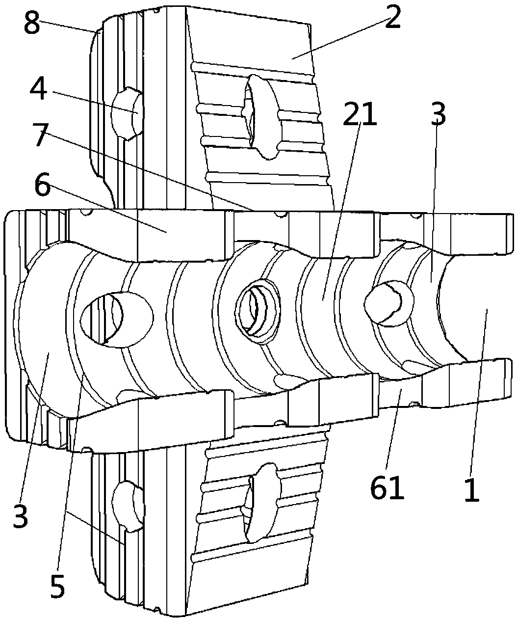
[0021] Such as figure 1 As shown, the fixing card used for building concrete reinforcement is composed of two connected C-shaped straight-through groove main bodies 21 on different planes that are vertically intersected. When in use, the reinforcement is pressed into the C-shaped groove 3 along the opening 1 for positioning. And fixed, instead of manually binding steel bars with thin steel wires.

[0022] The main bodies 21 of the C-shaped straight through grooves are straight through grooves, and the non-opening sides of the two C-shaped straight through groove bodies 21 intersect perpendicularly with each other, and the openings 1 of the two C-shaped straight through groove main bodies 21 are all facing outward. A C-shaped slot 3 is provided in each C-shaped through-slot main body 21 , and a through hole 4 is provided on the C-shaped through-slot main body 21 . Wherein, the through hole 4 is circular or elliptical, so that the concrete slurry can contact the steel bar throu...

Embodiment 2

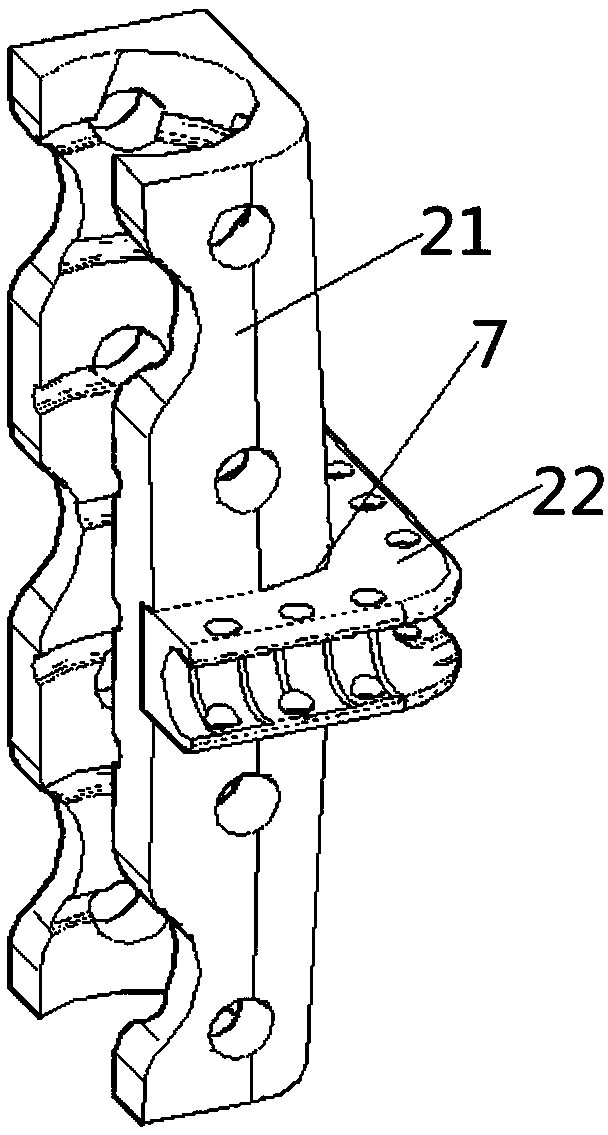
[0027] Such as figure 2 As shown, the fixing card used for building concrete reinforcement is composed of a C-shaped straight-through groove main body 21 and a C-shaped right-angle groove main body 22, and the non-open side of the C-shaped right-angle groove main body 22 is fixed on the C-shaped straight groove The non-open side of the main body 21 . The non-opening sides of the C-shaped straight-through groove main body 21 and the C-shaped right-angle groove main body 22 perpendicularly intersect each other, and the vertical intersection 7 is a right-angled surface.

[0028] Wherein, the apertures of the respective C-shaped grooves 3 of the C-type straight-through groove main body 21 and the C-shaped right-angle groove main body 22 are different; the aperture of the C-shaped groove 3 is designed according to the diameter of the steel bar being pressed in, and the steel bar that is pressed in is required to be the same as the C-shaped groove. Groove 3 is a tight fit. The po...

Embodiment 3

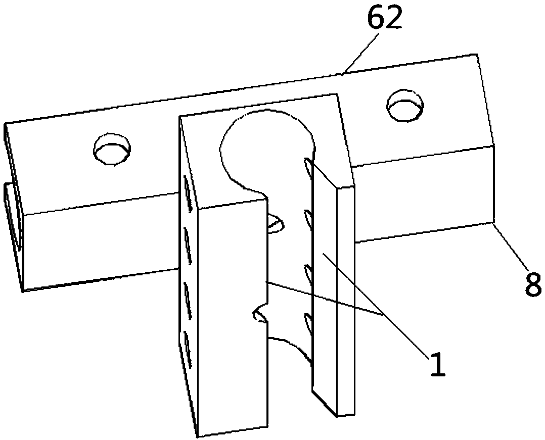
[0031] Such as image 3 As shown, the fixing card used for building concrete reinforcement is composed of two connected C-shaped straight-through groove main bodies 21 on different planes that are vertically intersected. When in use, the reinforcement is pressed into the C-shaped groove 3 along the opening 1 for positioning. And fixed, instead of manually binding steel bars with thin steel wires. The structure of embodiment 3 is similar to that of embodiment 1, except that the two sides 6 of the main body 21 of the C-shaped straight through groove are right-angled sides 62 . The end portion 8 of the C-shaped straight through groove main body 21 is a right angle. The opening 1 of the main body 21 of the C-shaped straight through groove is an asymmetrical opening, as long as the steel bars can be fixed smoothly.

[0032] The fixing clip for building concrete reinforcement is made of metal materials, high molecular polymer materials, recycled high molecular polymer materials or...


PUM


Abstract

The invention discloses a fixing clamp for building concrete reinforcing bars and belongs to the field of building components and waste resource utilization. The fixing clamp for the building concrete reinforcing bars comprises two C-shaped groove bodies, namely the C-shaped direct-through groove body and the C-shaped right-angle groove body. Each C-shaped groove body is internally provided with a C-shaped groove, wherein the C-shaped groove in the C-shaped direct-through groove body is in a linear mode, and the C-shaped groove in the C-shaped right-angle groove body is in a right-angle mode. The fixing clamp for the building concrete reinforcing bars can achieve positioning and fixation of the reinforcing bars and reinforcing bar nets placed on any plane as well as the reinforcing bars and reinforcing bar nets arranged in a perpendicularly crossed mode or in other modes, the reinforcing bars are positioned and fixed by directly pressing any point of each reinforcing bar, the fixing clamp is convenient to use and can replace the mode that the reinforcing bars are manually bound with steel wires, and accordingly construction progress and quality are improved. The structural model is symmetrical, and usage is easy.

Description

technical field [0001] The invention belongs to the field of building components and waste resource utilization, and in particular relates to a fixing clip for building concrete reinforcement bars. Background technique [0002] Steel bars are widely used in architectural concrete, and their position in concrete seriously affects the mechanical properties of buildings. Before concrete pouring, the steel bars and steel mesh must be positioned and fixed to prevent the steel bars and steel mesh from moving during the concrete pouring process and ensure the quality of reinforced concrete; the traditional fixing and positioning of steel bars are mostly manual binding, which is labor-intensive. time consuming. [0003] In the prior art, the ordinary steel bar support needs to be inserted from both ends of the steel bar, and the volume is relatively large; the improved "H" type steel bar support can only support horizontally placed steel bars, and is not suitable for steel bars pla...

Claims


Application Information

Patent Timeline
Patent Type & Authority Patents(China)
IPC IPC(8): E04C5/16E04C5/20
CPCE04C5/16E04C5/20
Inventor 程俊华程海军蔡树元吴忠原
Owner YANCHENG INST OF TECH
Learn More