Eureka AIR delivers breakthrough ideas for toughest innovation challenges, trusted by R&D personnel around the world.

Locking structure

A locking structure and locking shaft technology, applied in manual mechanisms, building structures, power control mechanisms, etc., can solve the problems of different locking forces of locks, poor sealing and heat insulation effects, and inconvenient practical application, etc. Stable and reliable structure, balanced locking and sealing, and excellent sealing effect

Active Publication Date: 2017-03-22
SICHUAN SCI CITY NEW ARK SECURITY TECH
View PDF4 Cites 0 Cited by
  • Summary
  • Abstract
  • Description
  • Claims
  • Application Information

AI Technical Summary

Problems solved by technology

[0002] The doors of existing rescue cabins generally have the problems of complex structure of opening and closing mechanism, poor sealing and heat insulation effects, water pressure and air tightness cannot meet the requirements, and manual and electric simultaneous closing and locking cannot be realized.
[0003] Especially for larger hatches, because of the large area, it is impossible to achieve the compression and sealing of the overall hatch only by relying on locks and hinges to fix and seal when sealing. Although some problems can be solved by adding locks and strengthening methods, but for larger The large plane of the hatch, the locking force of each lock is different, the locking effect cannot meet the requirements, and the practical application is also very inconvenient

Method used


Image

  • Locking structure
  • Locking structure

Examples


Embodiment Construction

[0024] The present invention is specifically described below by way of embodiment, and present embodiment is only used to further illustrate the present invention, but can not be interpreted as the restriction to protection scope of the present invention, some non-compliances that those skilled in the art make according to the content of the present invention above-mentioned Essential improvements and adjustments also belong to the protection scope of the present invention.

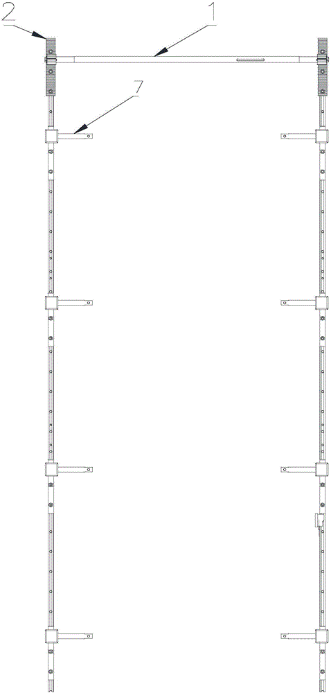
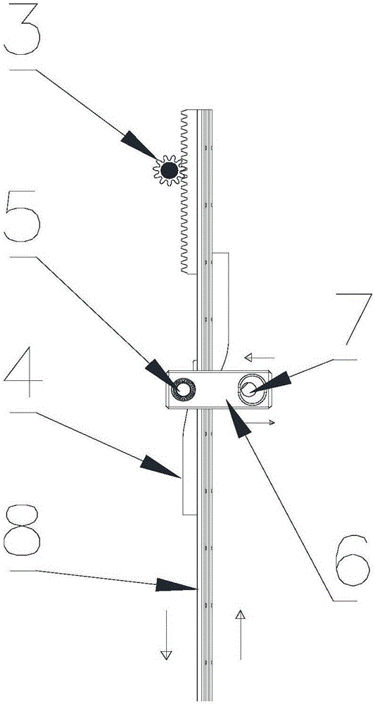
[0025] combine figure 1 , figure 2 .

[0026] As shown in the figure, the locking structure includes an openable part and a fixed part. The openable part and the fixed part are hinged to realize opening and closing. The openable part and the fixed part are also provided with a locking device. The locking device includes: The shaft 1 and the transmission gear 3, the transmission shaft 1 rotates around the axial direction, and the transmission gear 3 is respectively arranged at both ends of the transmiss...


PUM


Abstract

The invention discloses a locking structure. The locking structure comprises a transmission shaft and transmission gears. The transmission gears are arranged at the two ends of the transmission shaft. Two sets of guiding rails are arranged along a joint part of an openable component and a fixing component and comprise transmission racks and the transmission gears engaged with the transmission racks, and a plurality of sets of tightening mechanisms are arranged on the guiding rails at intervals. Each tightening mechanism is composed of a frapping piece, sliding blocks, a locking shaft and a back locking pin, wherein the frapping piece is located on the side of the joint part of the openable component and the fixing component, the front part of the frapping piece is vertically and fixedly connected with the locking shaft in the axial direction, and a lock hole used for enabling the back lock pin to vertically insert in is formed in the rear part of the frapping piece; and the two sliding blocks with inclined faces are fixedly arranged between the locking shaft and the back lock pin and on the two surfaces of the corresponding guide rail. The locking structure is stable in structure and high in reliability and sealing performance, and manual and power-driven back locking and compressing can be achieved. The locking structure can be arranged on a relatively large cabin door plane in a balancing manner and can achieve unlocking and locking linkage, opening and closing of a cabin door are more convenient, locking and sealing are balanced, and the sealing effect is more excellent.

Description

technical field [0001] The invention belongs to the technical field of mechanical design and manufacture, in particular to the design and manufacture of a locking mechanism for a door, and in particular to a locking and sealing structure for a security life-saving device. Background technique [0002] The doors of the existing rescue cabins generally have the problems of complex structure of the opening and closing mechanism, poor sealing and heat insulation effects, water pressure and air tightness cannot meet the requirements, and manual and electric simultaneous closing and locking cannot be realized. [0003] Especially for larger hatches, because of the large area, it is impossible to achieve the compression and sealing of the overall hatch only by relying on locks and hinges to fix and seal when sealing. Although some problems can be solved by adding locks and strengthening methods, but for larger With a large plane door, the locking force of each lock is different, th...

Claims


Application Information

Patent Timeline
Patent Type & Authority Applications(China)
IPC IPC(8): E05F15/622E05F11/54
CPCE05F11/54E05F15/622
Inventor 唐建军雍行
Owner SICHUAN SCI CITY NEW ARK SECURITY TECH
Why Eureka
Eureka Blog
Learn More