Top suction type extractor hood

A range hood, top suction technology, applied in the direction of removing oil fume, heating method, household heating, etc., can solve the problems of hindering the internal flow of gas, external air disturbance, air pollution, etc., to prevent oil fume from escaping, improving the effect, and improving The effect of efficiency

Active Publication Date: 2017-03-22
NINGBO FOTILE KITCHEN WARE CO LTD
View PDF7 Cites 7 Cited by
  • Summary
  • Abstract
  • Description
  • Claims
  • Application Information

AI Technical Summary

Problems solved by technology

The disadvantage of this technology is that the air curtain blocks the flow of gas to the inside of the range hood while isolating the oil fume, making it difficult to capture the oil fume that escapes to the periphery, so as to escape; in addition, the circulation path of the air curtain includes: 1. Centrifugal fan- --V-shaped groove---exhaust flue outlet-indoor---centrifugal fan; 2. Centrifugal fan---air curtain outlet---oil fume inlet----exhaust flue outlet---indoor--- Centrifugal fan; 3. Oil fume inlet----exhaust flue outlet----indoor---fume inlet, this circulation method will cause indoor environment pollution
[0007] There is also a Image 6 As shown in the range hood with ejection device, the fan 1' of the ejection device enters the air from the outside of the range hood, and generates a certain negative pressure suction effect on the external oil fume, so that the oil fume in a critical state is blown by the fan. , escape to the outside of the range hood, contact with the human body, and be absorbed by the human body, resulting in air pollution and affecting health; in addition, sucking air from the outside of the range hood will easily cause disturbance of the external air, which will easily cause the fume to escape

Method used


Image

  • Top suction type extractor hood
  • Top suction type extractor hood
  • Top suction type extractor hood

Examples


Embodiment 1

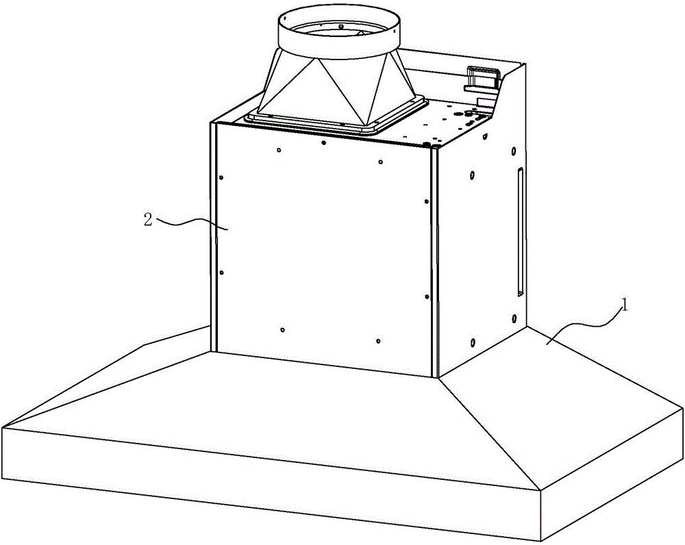
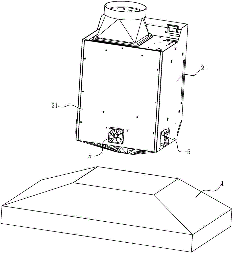
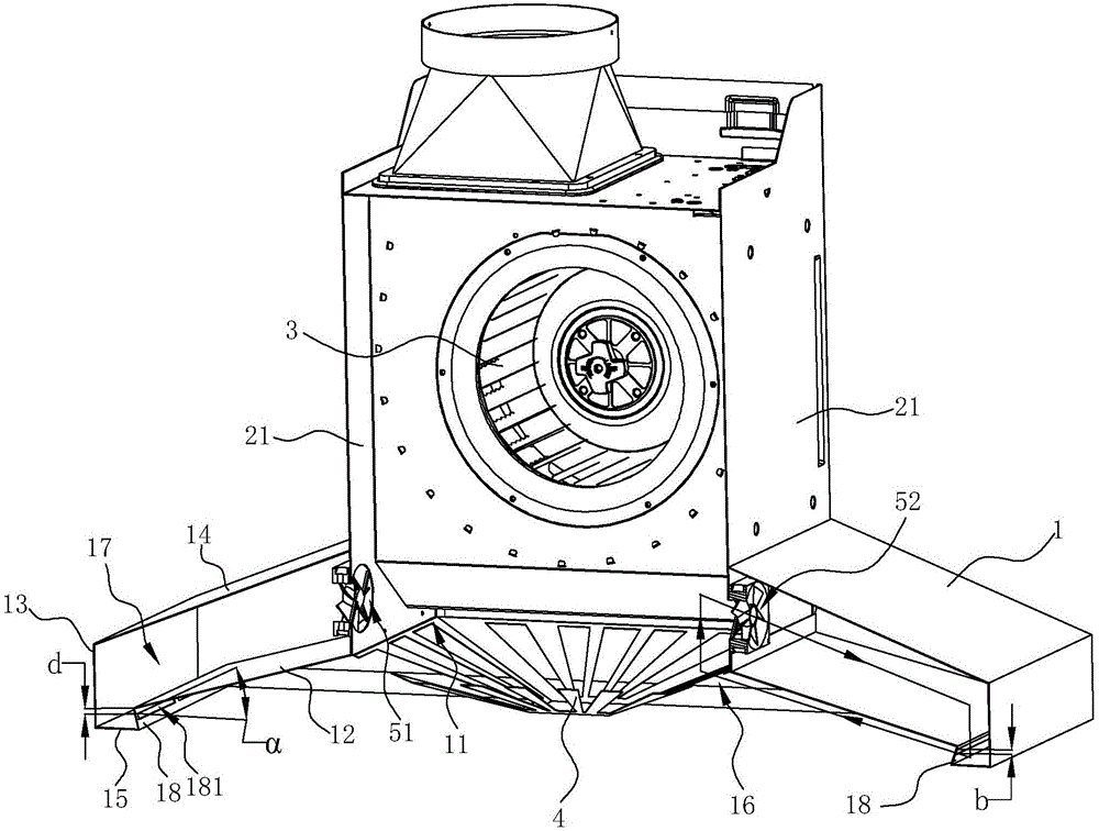
[0027] see Figure 1 ~ Figure 4 , a top-suction range hood, including a smoke collection hood 1, a fan cover 2 arranged above the smoke collection hood 1, and a main fan 3 arranged in the fan cover 2. An air inlet 11 is opened on the fume collecting hood 1, and the fume gas is sucked in from the air inlet 11, and is discharged into the public flue through the main fan 3. The fan cover 2 includes four side walls 21 forming a square fan cover 2 .

[0028] The smoke collecting hood 1 includes a lower cover plate 12, vertical side plates 13, an upper cover plate 14 and a horizontal bottom plate 15. The above-mentioned air inlet 11 is opened in the middle of the lower cover plate 12, and the lower cover plate 12 is upward from the outer edge to the middle. Inclined, thereby forming a smoke collecting cavity 16 under the lower cover plate 12 . The outer edge of the lower cover plate 12 is connected to the inner edge of the bottom plate 15, and the outer edge of the bottom plate 15...

Embodiment 2

[0035] see Figure 5 , in this embodiment, the difference from the first embodiment above is that the auxiliary fan 5 adopts a centrifugal fan instead of a centrifugal fan. At this time, there are two centrifugal fans arranged at the front end, which are respectively close to the left and right sides, and the left centrifugal fan Blow air in the cavity 17 on the left side, while the centrifugal fan on the right side blows air in the cavity 17 on the right; .


PUM


Abstract

The invention discloses a top suction type extractor hood which comprises an exhaust fume collecting hood and an auxiliary fan for injection. The exhaust fume collecting hood is concaved upwards to form an exhaust fume collecting cavity. The exhaust fume collecting hood is provided with an air inlet. A cavity is formed around the air inlet in the exhaust fume collecting hood. An air outlet of the auxiliary fan faces towards the interior of the cavity. The bottom of the outer side of the cavity is provided with an injection air outlet which faces towards the air inlet in an upward inclined mode. The top suction type extractor hood is characterized in that the lowest point of the air inlet of the auxiliary fan is not lower than the air inlet of the exhaust fume collecting hood, and sucks gas entering the air inlet of the exhaust fume collecting hood, and the cavity, the injection air outlet, the exhaust fume collecting cavity, the air inlet of the exhaust fume collecting hood and the auxiliary fan form a circulation flow path for gas circulation flow. Gas circularly flows in the circulation flow path, negative pressure is produced, rising exhaust fume is guided to flow and be gathered towards the air inlet of the extractor hood, the exhaust fume collecting effect is greatly improved, and exhaust fume is prevented from being escaping.

Description

technical field [0001] The invention relates to a range hood, in particular to a top suction type range hood. Background technique [0002] At present, most of the existing top-suction range hoods (thin, deep or tower range hoods installed directly above the cooker, excluding side suction and bottom row types) are mostly in the form of a smoke collecting hood on the top. The inner concave cavity (smoke collecting cavity), and the smoke collecting hood is provided with an air inlet and a filter screen. Oil fumes generated during the cooking process are collected in the smoke collecting chamber and discharged outside through the air duct communicating with the smoke collecting chamber. [0003] For example, the Chinese patent application with application number 201410315985.7 discloses a top-suction range hood, which includes a smoke collection hood and an air inlet arranged on the bottom of the smoke collection hood. Constitutes four-side air intake channels, and the shroud...

Claims


Application Information

Patent Timeline
Patent Type & Authority Applications(China)
IPC IPC(8): F24C15/20
CPCF24C15/20
Inventor 李年平王军元贾博贤刘小祥茅忠群诸永定
Owner NINGBO FOTILE KITCHEN WARE CO LTD
Why Eureka
Try Eureka