Control circuit for reducing DC gain of internal module of computer

A DC gain and control circuit technology, applied in gain control, amplification control, protection of internal/peripheral computer components, etc., can solve problems such as improper DC signal filtering, DC offset, etc., to suppress DC offset and avoid saturation. Effect

Inactive Publication Date: 2017-03-22
ZHENGZHOU TIANSHUN ELECTRONICS TECH CO LTD
View PDF0 Cites 2 Cited by
  • Summary
  • Abstract
  • Description
  • Claims
  • Application Information

AI Technical Summary

Benefits of technology

The technical purpose described in this patented technology uses an improved version of Op-Amplifier (OpA) circuit called Single Ompum Design or LMU designed for better performance at high voltages compared to previous designs. This allows it to achieve more precise control over electrical characteristics such as impedance values and minimizing power consumption during operation.

Problems solved by technology

The technical problem addressed in this patented text relates to how to filter out unwanted electrical noise caused by electronic devices such as computers while still maintaining their effectiveness at high-frequency analog circuits (AC).

Method used


Image

  • Control circuit for reducing DC gain of internal module of computer

Examples


Embodiment Construction

[0011] The following will clearly and completely describe the technical solutions in the embodiments of the present invention with reference to the drawings in the embodiments of the present invention.

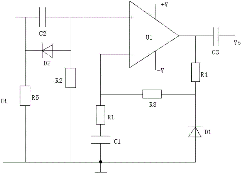
[0012] see figure 1 , in an embodiment of the present invention, a control circuit for reducing the DC gain of a computer internal module includes a diode D1, a capacitor C1, a resistor R1, an operational amplifier U1, a capacitor C2, and a resistor R2, and one end of the capacitor C2 is respectively connected to one end of the AC power Ui, Resistor R5 and the negative pole of diode D2, the other end of capacitor C2 are respectively connected to resistor R2, the positive pole of diode D2 and the same phase end of op amp U1, the inverting end of op amp U1 is respectively connected to resistor R1 and resistor R3, the other end of resistor R1 is connected to capacitor C1, capacitor C1 The other end is respectively connected to the positive pole of the diode D1, the other end of t...


PUM


Abstract

The invention discloses a control circuit for reducing DC gain of an internal module of a computer. The control circuit comprises a diode D1, a capacitor C1, a resistor R1, an operational amplifier U1, a capacitor C2 and a resistor R2, wherein one end of the capacitor C2 is respectively connected to one end of alternating current Ui, a resistor R5 and a cathode of the diode D2 and the other end of the capacitor C2 is respectively connected to the resistor R2, an anode of the diode D2 and a non-inverting terminal of the operational amplifier U1; an inverting terminal of the operational amplifier U1 is respectively connected to the resistor R1 and a resistor R3; and the other end of the resistor R1 is connected to the capacitor C1. The control circuit adopts design of the single operational amplifier U1 and introduces DC complete feedback and AC partial feedback, when the AC voltage gain is larger, the DC voltage gain is very small, so that the saturation of the operational amplifier due to input offset current is avoided, and furthermore, the voltage stabilizing diode D1 is arranged to clamp the maximal amplitude of the voltage at the output end in order to suppress the DC offset.

Description


Claims


Application Information

Patent Timeline
Owner ZHENGZHOU TIANSHUN ELECTRONICS TECH CO LTD
Why Eureka
Try Eureka