A filter apparatus for filtering a stream of gas

A filter and gas flow technology, which is applied in membrane filters, dispersed particle filtration, chemical instruments and methods, etc., can solve the problems of inconvenient removal of filter cartridges, filter design limitations, and difficulty in handling, etc.

Active Publication Date: 2017-03-22
NORGREN LTD
View PDF4 Cites 6 Cited by
  • Summary
  • Abstract
  • Description
  • Claims
  • Application Information

AI Technical Summary

Problems solved by technology

However, in confined spaces, removal of the filter cartridge can be extremely inconvenient, and sufficient space must be left around the filter device to allow for maintenance
This extra space presents significant d

Method used


Image

  • A filter apparatus for filtering a stream of gas
  • A filter apparatus for filtering a stream of gas
  • A filter apparatus for filtering a stream of gas

Examples


Embodiment Construction

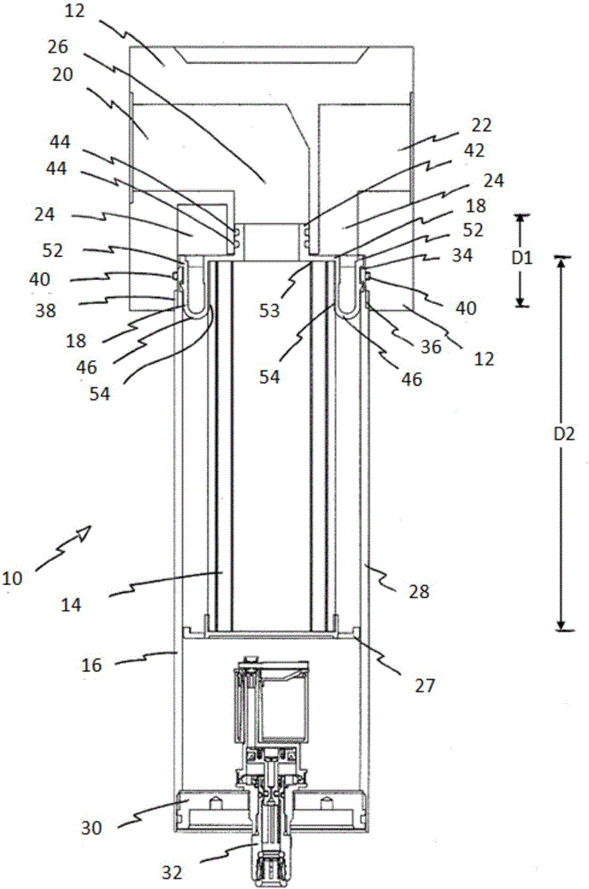
[0031] refer to figure 1 , shows a filter device 10, and this device is used to filter a gas flow. In particular, apparatus 10 is used to filter compressed air streams, which is typically performed prior to the drying step in compressed air purification processes. The four main components of the filter apparatus are the head end 12, the filter 14, the cartridge 16 and the connector 18 connecting the head end, filter and cartridge together.

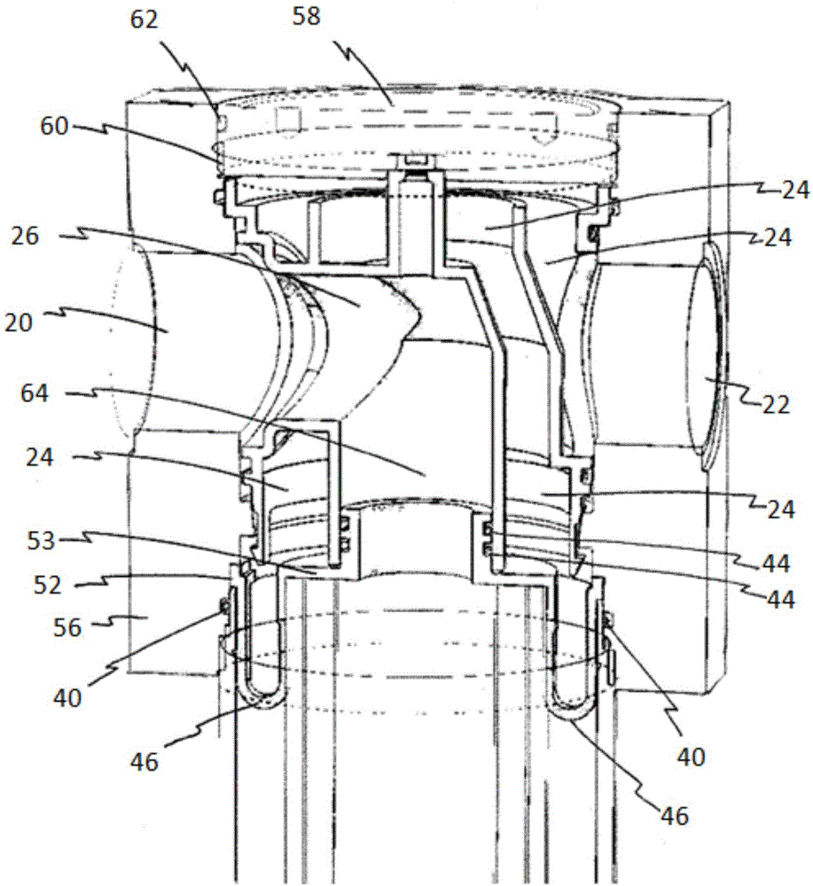
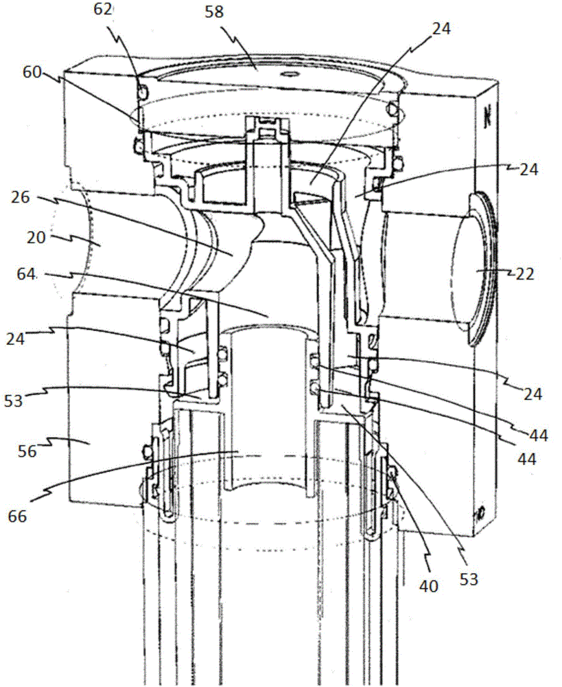
[0032] The filter head 12 has an inlet 20 for receiving a flow of compressed air. The head end 12 also has an outlet 22 through which compressed air passes to downstream equipment (not shown). Compressed air flows to and from the filter via a first conduit 24 and a second conduit 26 . The first conduit 24 substantially surrounds the second conduit 26, which enters the cartridge 16 and carries the filtered air flow to the outlet. A second conduit 26 is radially inward from the first conduit 24 and directs the flow of compressed air into...


PUM


Abstract

A filter apparatus for filtering a stream of gas is disclosed. The apparatus has a head with an inlet and an outlet, the head also having a first flow conduit connected to the inlet and a second flow conduit connected to the outlet. The apparatus also has a filter and a bowl which contains the filter and is connected to the head. The bowl has an annular recess. There is also a connector for connecting the filter to the head and the bowl. The part of the connector that engages the bowl has a protrusion that is inserted into the recess.

Description

technical field [0001] The present invention relates to a filter device for filtering a gas flow, and in particular, but not exclusively, to a device for filtering a compressed air flow. Background technique [0002] Compressed air is used throughout industry as a safe and reliable source of energy. However, the compressed air delivered directly from the compressor is of an unsuitable quality for most uses without treatment to improve its purity. Treating compressed air typically involves filtering it to remove oil and particles, and drying it to remove moisture. [0003] A typical example of a filter device comprises: a filter head containing an inlet and an outlet; and a cartridge threadedly engaging the head to form a sealed container within which filter components are housed. The filter element is typically a tube sealed at one end that is attached to the filter head and located within the filter cartridge. A pair of conduits formed in the filter head direct air to an...

Claims


Application Information

Patent Timeline
IPC IPC(8): B01D46/00B01D46/24
CPCB01D46/0004B01D46/2411B01D46/2414B01D2265/028B01D2265/05B01D46/0005B01D46/24B01D2265/027
Inventor C·比耶
Owner NORGREN LTD
Why Eureka
Try Eureka