Ablatable elements for making flexographic printing plates

a technology of flexographic printing plate and laser engraving, which is applied in the field of laser engraving elements, can solve the problems of poor beam resolution, slow and expensive use, and insufficient power of most imaging devices, and achieve the effect of reducing environmental and health hazards, and being easy to capture and dispose o

Inactive Publication Date: 2008-10-23
EASTMAN KODAK CO
View PDF26 Cites 60 Cited by
  • Summary
  • Abstract
  • Description
  • Claims
  • Application Information

AI Technical Summary

Benefits of technology

[0023]This invention provides a desirable method for producing relief images by laser ablation, such as providing relief images in flexographic printing plates. The laser-ablatable element includes a laser-ablatable material that can be broken down or “depolymerized” to form predominantly identifiable low molecular weight products (or monomer units in some cases) when subjected to laser imaging under conditions defined herein. The low molecular weight products produced by ablation of each laser-ablatable material can be readily captured and disposed of to reduce environmental and health hazards. In some instances, less debris (solid residue) is produced during imaging.

Problems solved by technology

Difficulties arise with this approach because most imaging devices have insufficient power to provide sufficient relief depth.
While they are generally slow and expensive to use and have poor beam resolution, they are used because of the attractions of direct thermal imaging.

Method used


Image

  • Ablatable elements for making flexographic printing plates
  • Ablatable elements for making flexographic printing plates
  • Ablatable elements for making flexographic printing plates

Examples


example 1

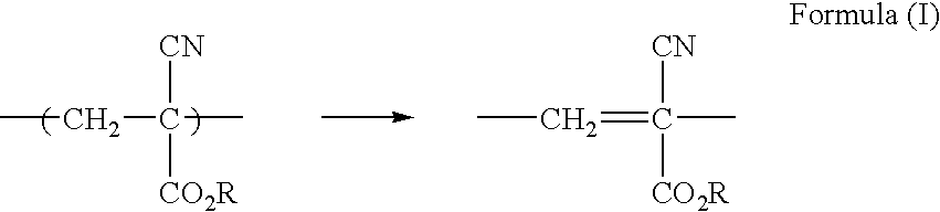
Preparation of Poly(Cyanoacrylate) Laser-Ablatable Element

[0085]A poly(ethoxyethyl-2-cyanoacrylate) solution containing a dispersion of carbon black particles was made as follows:

[0086]A vial was charged with Prism 408 (2.0 g, ethoxyethyl-2-cyanoacrylate), Mogul L carbon black (0.11 g, Cabot Corporation), and dichloromethane (5 g). The dispersion was sonicated using a commercially available horn ultrasonicator and polymerization was initiated by adding 1 drop of a solution of triethylamine (3 drops) in dichloromethane (10 ml). The resulting thick mixture was poured on a coating surface and drawn down with 40 mil (0.1 cm) shim and allowed to air dry overnight to give a smooth laser-ablatable layer on the substrate.

[0087]Pyrolysis GC / MS produced ethoxyethyl-2-cyanoacrylate monomer as the predominant low molecular weight product. Some methoxyethanol was also observed.

example 2

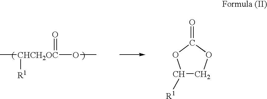
Preparation of Polycarbonate Laser-Ablatable Element

[0088]Poly(propylene carbonate) (2 g, 23,000 molecular weight), obtained from Novomer (Ithaca, N.Y.) was dissolved in dichloromethane (10 g) and mixed with Mogul L carbon black (0.11 g) and a catalyst (0.10 g) of interest (shown in TABLE I below and structures thereafter). The resulting dispersion was sonicated and then evaporated to about 50% solids. The resulting thick mixture was poured onto a coating surface and drawn down with 24 mil (0.06 cm) shim and allowed to air dry overnight to give a smooth laser-ablatable layer on the substrate.

TABLE IExample 2SamplesCatalystStructureANoneB(BP)AlOiPrCzinc glutarateD(BDIEt)ZnOAcE(BDIiPr)ZnOAcFPPNClG(salcy)CoOBzF5

[0089]Propylene carbonate was the predominant low molecular weight product observed by pyrolysis GC / MS. Small amounts of acetone, propanol, allyl alcohol, propylene glycol, and intact ligand from the catalyst were also observed.

[0090]A Comparative Element was prepared similarly ...

example 3

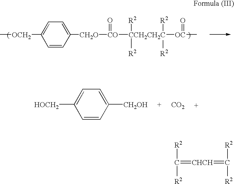
Preparation of Crosslinked Polycarbonate Laser-Ablatable Element

[0092]Poly(propylene carbonate) (2.25 g, 2,300 molecular weight, two hydroxyl end groups) obtained from Novomer (Ithaca, N.Y.) was dissolved in dichloromethane (1.21 g) and mixed with Mogul L carbon black (0.148 g, Cabot Corporation) and Desmodur® N3300 triisocyanate (0.38 g). The dispersion was sonicated and the resulting thick mixture was poured onto a coating surface and allowed to dry to form a crosslinked rubber. A sample added to THF swelled two times its original volume but did not dissolve in the solvent, indicating that crosslinking had occurred.

[0093]The coated sample was successfully imaged with a series of six laser ablation processes, each in a halftone pattern of dots centered on 780 μm spacing. The dot pattern of the six ablations was in a series of increasing dot size beginning at 120 μm and progressing through 210 μm, 300 μm, 390 μm, 480 μm, and 570 μm. The exposure sequence was designed to create a pyr...


PUM

PropertyMeasurementUnit
thicknessaaaaaaaaaa
weight %aaaaaaaaaa
thicknessaaaaaaaaaa

Abstract

Flexographic printing plates and other relief images can be formed from a laser-ablatable element having a laser-ablatable layer that is at least 20 μm in thickness. The laser-ablatable layer includes a film-forming material that is a laser-laser-ablatable material or the film-forming material has dispersed therein a laser-ablatable material. The laser-ablatable material is a polymeric material that when heated to 300° C. at a rate of 10° C./minute, loses at least 60% of its mass to form at least one predominant low molecular weight product. The element can be imaged by ablation at an energy of at least 1 J/cm2 to provide a relief image.

Description

RELATED APPLICATION[0001]The present application is a Continuation-in-part of copending and commonly assigned U.S. Ser. No. 11 / 738,536 that was filed Apr. 23, 2007 by Michael T. Regan, David B. Bailey, and Christine J. Landry-Coltrain.FIELD OF THE INVENTION[0002]This invention relates to laser-ablatable (or laser engravable) elements that can be used to prepare flexographic printing plates. It also relates to methods of making and using these elements.BACKGROUND OF THE INVENTION[0003]Flexography is a method of printing that is commonly used for high-volume printing runs. It is usually employed for printing on a variety of substances particularly those that are soft and easily deformed, such as paper, paperboard stock, corrugated board, polymeric films, fabrics, plastic films, metal foils, and laminates. Course surfaces and stretchable polymeric films can be economically printed by the means of flexography.[0004]Flexographic printing plates are sometimes known as “relief printing pla...

Claims


Application Information

Patent Timeline
Patent Type & Authority Applications(United States)
IPC IPC(8): B29C59/16B32B27/30B32B5/00
CPCB41C1/05B41M5/24Y10S430/145B41N1/12
Inventor REGAN, MICHAEL T.BAILEY, DAVID B.LANDRY-COLTRAIN, CHRISTINE J.
Owner EASTMAN KODAK CO
Why Eureka
Try Eureka