Linear actuator

A technology of linear actuators and motors, applied in the direction of transmissions, electric components, electromechanical devices, etc., can solve problems such as expensive and complicated prices

Inactive Publication Date: 2017-03-22
LINAK AS
View PDF15 Cites 0 Cited by
  • Summary
  • Abstract
  • Description
  • Claims
  • Application Information

AI Technical Summary

Problems solved by technology

Furthermore, this solution is slightly more complicated and slightly more expensive

Method used


Image

  • Linear actuator
  • Linear actuator
  • Linear actuator

Examples


Embodiment Construction

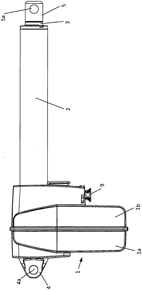
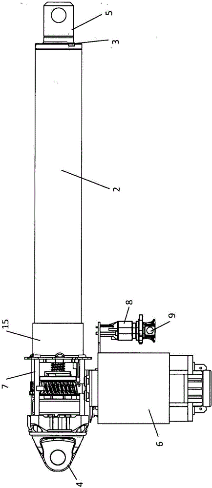
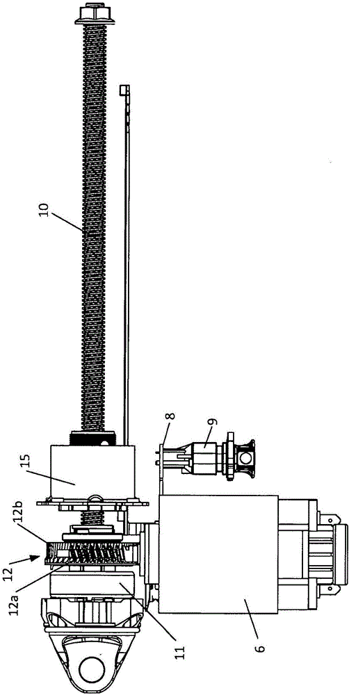
[0024] The linear actuator shown in the figures comprises a housing 1 consisting of a first part 1a and a second part 1b. Furthermore, the linear actuator comprises a catheter 2 and a tubular adjustment element 3 guided in said catheter 2 . For mounting the linear actuator, the rear end of the housing 1 is equipped with a rear mounting 4 and in the front end of the tubular adjustment element 3 a front mounting 5 is provided. Both the rear mounting part 4 and the front mounting part 5 have eyelets, through-holes 4a, 5a for bolts, rivets, pivot pins etc., by means of which the linear actuator can be fixed. The linear actuator is thus able to rotate around the central axis through the holes in the rear mount 4 and the front mount 5, so that the linear actuator automatically adapts the position of the two elements in the structure used to fix the linear actuator so that The force is always ideally transmitted axially along the longitudinal direction of the tubular adjustment elem...


PUM


Abstract

Linear actuator comprising a housing (1) with an electric motor (6), which through a transmission (12) drives a spindle (10) with a spindle nut (13). To the spindle nut (13) is secured a tubular adjustment element (3), which is guided in a guide tube (2). A bushing (15) is secured at the rear end of the guide tube (2) by means of which the guide tube (2) is secured to the chassis (7) of the actuator. Expediently, the securing is done with stampings (16) from the outer side of the mounting bushing (15) and into the guide tube (2). These stampings (16) are appropriately done opposite channels, such as screw channels (17) in the guide tube (2), such that the stampings (16) are received in the channels and moreover do not in a disrupting manner protrude into the guide tube (2) and prevent the movement of the spindle nut (13) and the adjustment element (3), respectively.

Description

technical field [0001] The invention relates to a linear actuator comprising: a housing; an electric motor; a transmission; a spindle interconnected with the transmission; a spindle nut on the spindle; The rear end of the adjustment element is connected to the spindle nut; a conduit for the tubular adjustment element, wherein the rear end of the conduit is screwed to the chassis of the actuator. Background technique [0002] Probably the most common type of linear actuator includes a front mount on the front end of the tubular adjustment element and a rear mount in the rear end of the housing for mounting the actuator. The forces generated by the load are guided via the tubular adjusting element, the spindle nut and the spindle as a compressive or tensile force between the rear mounting and the front mounting. When subjected to compression, the tubular adjustment element and the mandrel are thereby affected to deflect. In particular, there are potential "break points" at w...

Claims


Application Information

Patent Timeline
Patent Type & Authority Applications(China)
IPC IPC(8): F16H25/20
CPCF16H25/20F16H2025/204F16H2025/2031F16H2025/209H02K5/04H02K7/06H02K7/1166
Inventor R·瑟伦森
Owner LINAK AS
Why Eureka
Try Eureka