This helps you quickly interpret patents by identifying the three key elements:
Problems solved by technology
Method used
Benefits of technology
Problems solved by technology
However, the structure of the laminated battery in Patent Document 1 has a bag portion near the tab portion serving as an electrode terminal. Therefore, when a battery pack is formed and a plurality of laminated batteries are connected, it is difficult to arrange them in any direction. Gas tends to flow back toward the tab, and as a result, there is a risk of gas leakage from the tab and frequent malfunction of the battery, and there is room for improvement.
Method used
Image
Click on the blue label to locate the original text in one second.
Reading with bidirectional positioning of images and text.
Examples
manufacture example
[0268] As the positive electrode active material used in the positive electrode of Manufacturing Example 1, spinel-type lithium manganate (Li 1.1 Al 0.1 mn 1.8 o 4 ).
[0269] Spinel-type lithium manganese oxide (Li 1.1 Al 0.1 mn 1.8 o 4 ), the conductive auxiliary material (acetylene black) and the solid content concentration of the binder (PVdF) are respectively 100 parts by weight, 5 parts by weight and 5 parts by weight of a mixture of slurry. At this time, the binder used was an N-methyl-2-pyrrolidone (NMP) solution adjusted to a solid content concentration of 5 wt%. In order to facilitate the coating described later, NMP was further added to measure the viscosity Adjustment.
[0270] After applying this slurry to an aluminum foil (15 μm), it was dried to remove the solvent. A positive electrode was fabricated by implementing the above steps on both sides of the aluminum foil.
[0271] (Manufacturing example of negative electrode)
[0272] As the negative elect...
Embodiment 1
[0279] (Example 1: Manufacturing example of assembled battery)
[0280] Created using the method described below Figure 12 battery pack shown.
[0281] First, if Figure 4 As shown, the above-mentioned laminated batteries 2 are arranged vertically and horizontally to the stacking direction of the laminated body, that is, two of the above-mentioned laminated batteries 2 are arranged in the stacked layer of the laminated body, and on one main surface 36 thereof The positive electrode terminals 5a were electrically connected to each other, and the negative electrode terminals 5b were electrically connected to each other on the other main surface, thereby producing a laminated battery primary assembly 35 in which one series and two parallels were connected.
[0282] It should be noted that, in this embodiment, in order to maintain the shape of the laminated battery primary assembly 35, as Figure 4 As shown, using a polypropylene plate (25 cm in length, 30 cm in width, and 0.1...
Embodiment 2
[0286] (Example 2: Manufacturing Example of Electric Storage Unit)
[0287] Next, the battery pack 1f prepared in Example 1 was arranged in three rows in the horizontal direction (the first row is divided into four stages in the vertical direction, and the second and third rows are divided into three stages in the vertical direction), thereby producing An electric storage unit 100a in which ten assembled batteries 1f are electrically connected in series. Figure 13 It is a schematic diagram of the above-mentioned electric storage unit 100a.
[0288] The above-mentioned electric storage unit 100a is an electric storage unit in which 100 laminated batteries 2 connected in parallel are connected in series, and is also an electric storage unit in which ten assembled batteries 1f of the present invention are connected in series. Such electric storage cells 100a are also referred to as "100 series and 2 parallel" on the basis of laminated batteries.
[0289] Therefore, the above-m...
PUM
Property
Measurement
Unit
hardness
aaaaa
aaaaa
hardness
aaaaa
aaaaa
Abstract
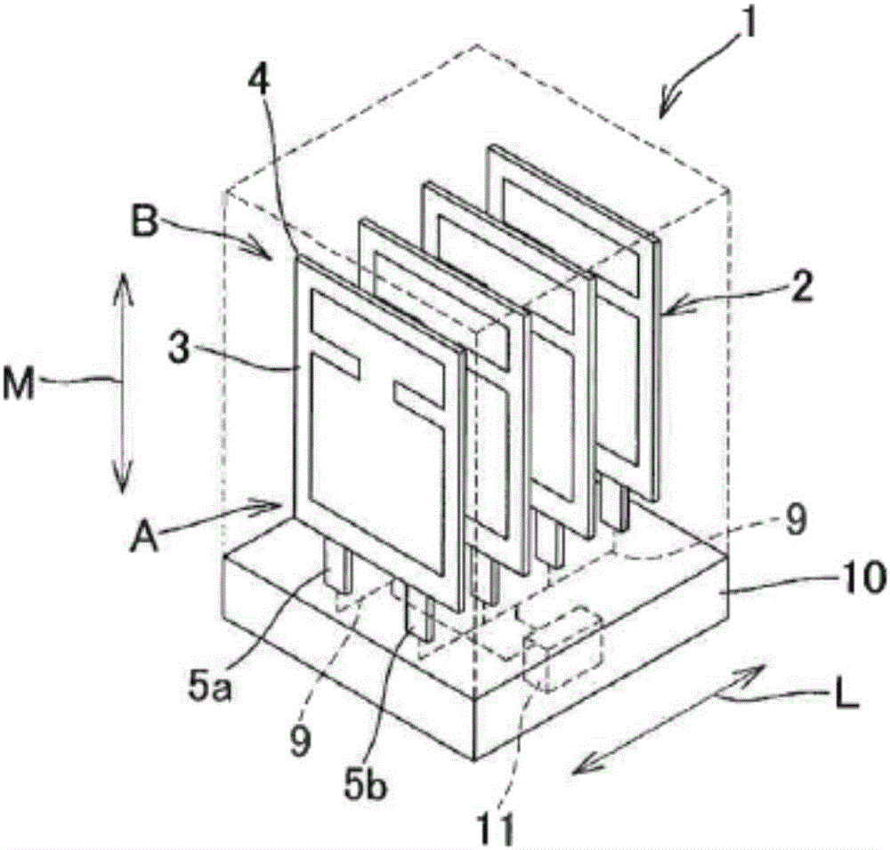
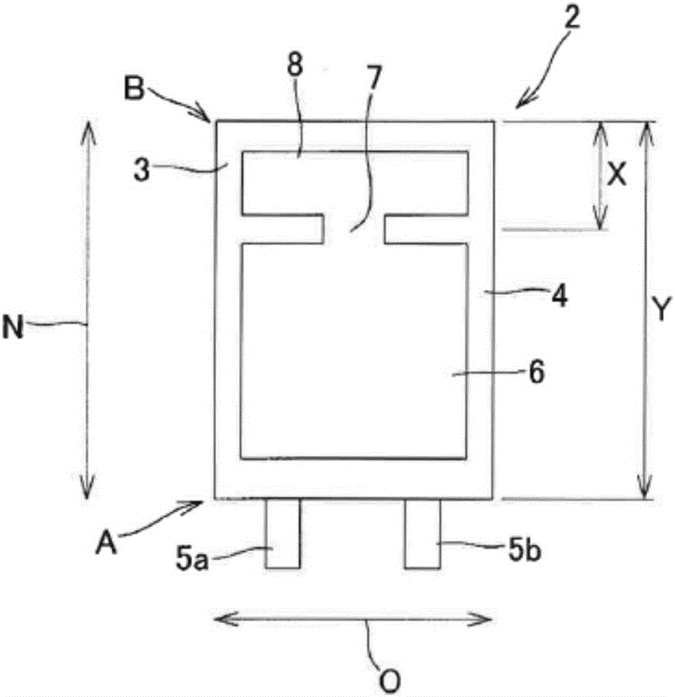
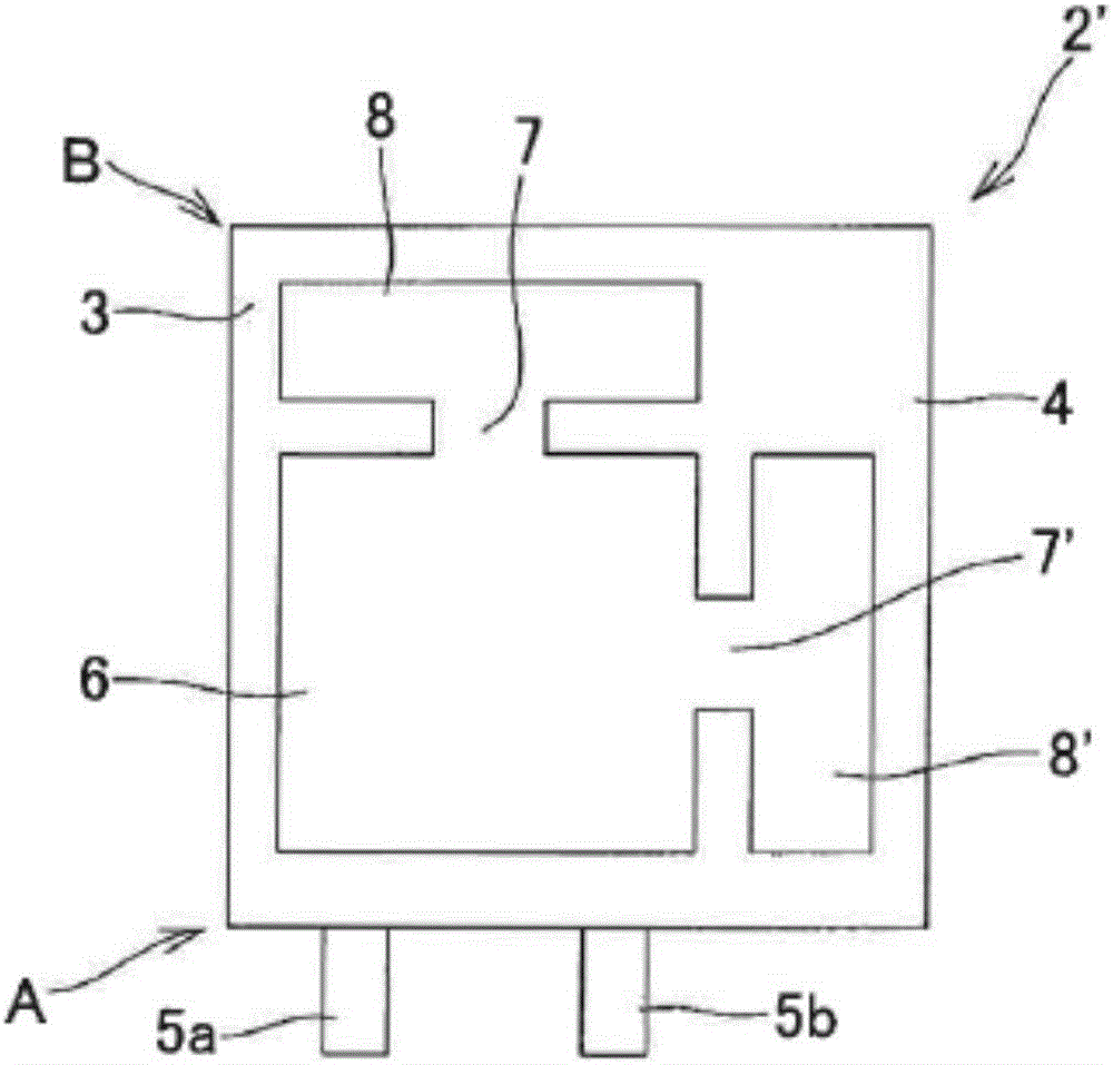
Provided is a cell pack in which a plurality of plate-shaped laminated cells are aligned in a direction perpendicular to plate-shaped surfaces of the laminated cells. The cell pack is characterized in that: each laminated cell comprises a laminated body of a negative electrode-separator-positive electrode disposed parallel to the plate-shaped surface of the laminated cell, a casing comprising a laminated film in which the laminated body is sealed, and electrode terminals which are electrically connected to the laminated body and extend out from one side of the casing; the casing includes therein a cell part which is a space in which the laminated body exists, and a pocket part which is a variable-volume space in communication with the cell part through a communication part and is disposed on the other side opposite to the aforementioned one side; the cell pack is configured in such a way that the laminated cells are aligned so that the other side is disposed on an upper surface in the vertical direction thereof and the one side is disposed on a lower surface in the vertical direction thereof; and furthermore, a power cable for charging and discharging the cell pack is disposed on the lower surface in the vertical direction. The cell pack is highly reliable and exhibits excellent operating stability, i.e., maintains high efficiency.
Description
technical field [0001] The present invention relates to a battery pack, and more specifically, to a battery pack in which a plurality of flat laminated batteries are stacked. Also, it relates to an electric storage unit including a plurality of assembled batteries. Background technique [0002] Laminated batteries are known to degrade battery performance due to gas generated during charge-discharge cycle operation. In order to avoid this problem, for example, Patent Document 1 has developed a technique of trapping gas by arranging a pouch portion on one side of a laminated battery using the electrode. However, the structure of the laminated battery in Patent Document 1 has a bag portion near the tab portion serving as an electrode terminal. Therefore, when a battery pack is made and a plurality of laminated batteries are connected, it is difficult to arrange them in any direction. Gas tends to flow back toward the tab portion, and as a result, gas leakage from the tab port...
Claims
Application Information
Patent Timeline
Application Date:The date an application was filed.
Publication Date:The date a patent or application was officially published.
First Publication Date:The earliest publication date of a patent with the same application number.
Issue Date:Publication date of the patent grant document.
PCT Entry Date:The Entry date of PCT National Phase.
Estimated Expiry Date:The statutory expiry date of a patent right according to the Patent Law, and it is the longest term of protection that the patent right can achieve without the termination of the patent right due to other reasons(Term extension factor has been taken into account ).
Invalid Date:Actual expiry date is based on effective date or publication date of legal transaction data of invalid patent.

