Paper feeding device and image forming device provided with same

A paper feeding and image technology, applied in the direction of object supply, transportation and packaging, thin material processing, etc., can solve the problems of uneven rollers, poor conveying, wrinkles, etc., and achieve the effect of avoiding speed difference and high-speed conveying

Active Publication Date: 2017-03-29
KONICA MINOLTA INC +1
View PDF6 Cites 2 Cited by
  • Summary
  • Abstract
  • Description
  • Claims
  • Application Information

AI Technical Summary

Problems solved by technology

[0005] However, since the speed of the conveying roller is different from that of the pick-up roller (the speed of the conveying roller>the speed of the pick-up roller), when the paper is transferred from the pick-up roller to the conveying roller, there is a problem that the paper is The force of the paper (such as tension, etc.) is generated due to the difference in speed, and the load of this force affects the conveying roller and the paper pick-up roller, so that conveyance failure is likely to occur
[0006] For example, when the conveying roller and the paper lifting roller are subjected to the above-mentioned tension, the rollers are subjected to uneven force in the axial direction, which makes the paper inclined relative to the conveying direction, so that paper jams or paper wrinkles are likely to occur
Also, there is the issue of damaged paper
For example, if the above-mentioned tension is strong, there is a possibility that the paper will be torn
Also, for example, when the paper is picked up using the separation claw method, the paper also exerts a load on the separation claw due to the above-mentioned force of the paper, and this load may cause damage to the paper

Method used


Image

  • Paper feeding device and image forming device provided with same
  • Paper feeding device and image forming device provided with same
  • Paper feeding device and image forming device provided with same

Examples


Embodiment approach 1

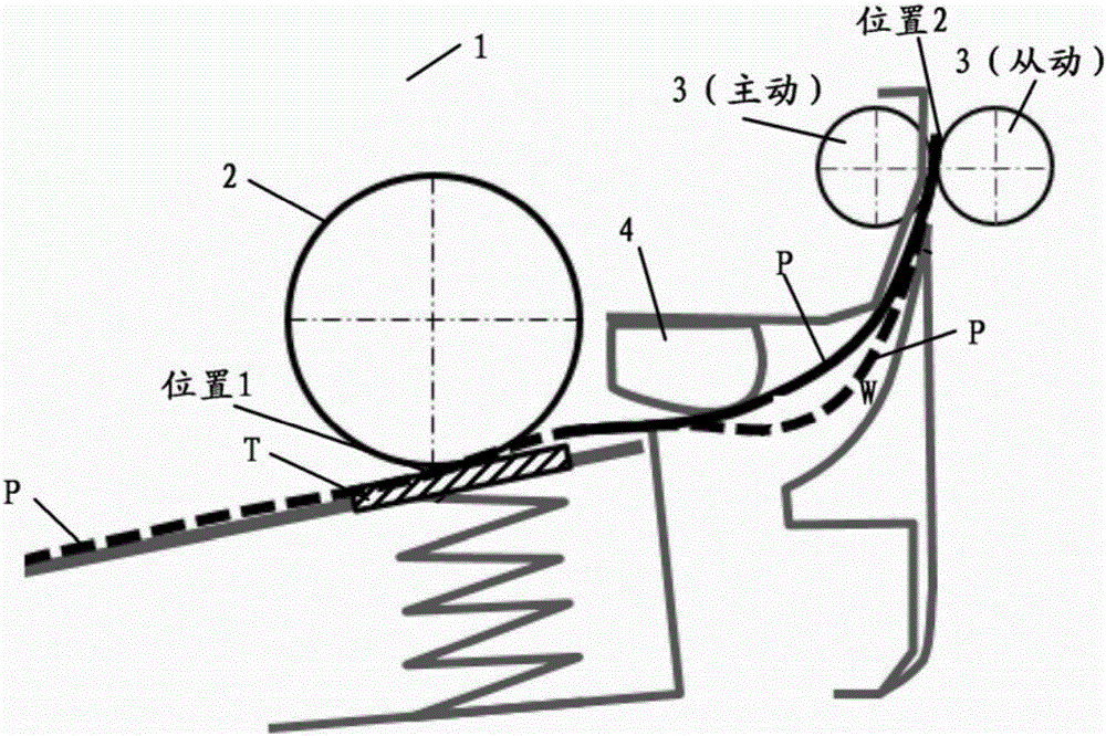
[0048] figure 1 A schematic diagram of the paper feeding device 1 of the present invention is shown. The paper feeding device 1 can be installed in devices such as printers, copiers, and composite machines, and is used for paper feeding.

[0049] Such as figure 1As shown, the paper feeding device 1 of the present invention picks up the paper P placed on the paper feeding tray T. The paper feeder 1 includes a pick-up roller 2 and a transport roller 3 positioned downstream in the paper transport direction relative to the pick-up roller 2 , and the paper P on the paper feed tray T is picked up one by one by the pick-up roller 2 . There is an elastic member such as a spring under the paper feeding tray T, which exerts force on the paper feeding tray T to ensure that the paper can contact the paper lifting roller 2 and be picked up.

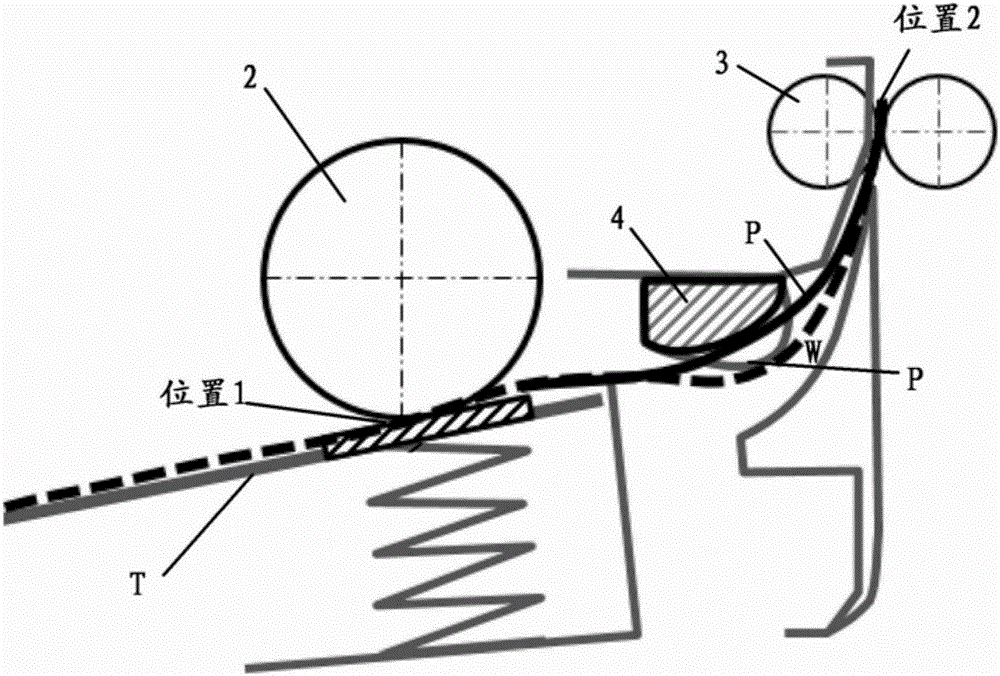
[0050] During the paper feeding operation, the paper P is picked up from the paper feeding tray T by the paper lifting roller 2, and at position 1...

Embodiment approach 2

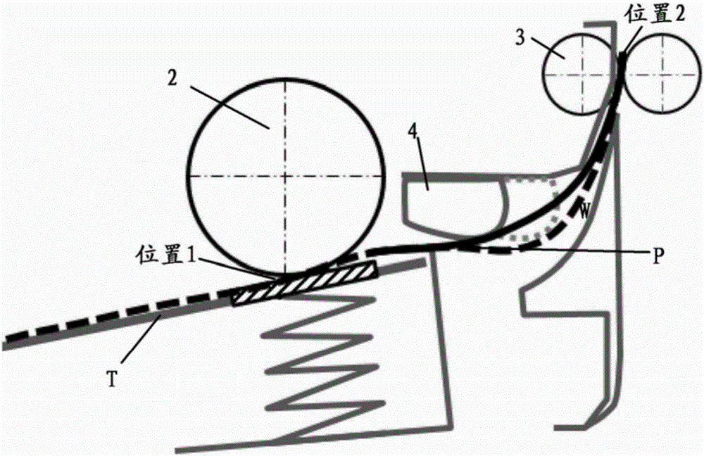
[0088] Figure 9 The paper feeding device 10 of Embodiment 2 is shown. In this embodiment, the difference from Embodiment 1 is that the shape of the pick-up roller 20 of the paper feeding device 10 is an incomplete circle or a cam shape. By making the paper lifting roller 20 form an incomplete circle or cam shape, its effective arc surface is no longer the entire circumference of the outer circumference of the paper lifting roller, but a section of arc surface (arc surface less than 360 degrees) . And, when the paper lifting roller 20 rotates from one end of the effective arc surface to the other end, the process of extracting a piece of paper from the paper feeding tray and conveying the paper P1 to the position of the conveying roller 30 is completed. Afterwards, since the extraction roller 20 is an incomplete circle, it turns to the area of ​​the non-effective arc surface, so that it does not contact the paper P1, and the paper P1 is continuously conveyed by the conveying ...


PUM


Abstract

The invention provides a paper feeding device and an image forming device provided with the same. The paper feeding device (1) is provided with a paper lifting roller (2), carrying rollers (3), a carrying guide rail (4) and a bend forming part (W), wherein the paper lifting roller (2) is used for lifting paper (P); the carrying rollers (3) are located on the downstream side in the paper carrying direction relative to the paper lifting roller (2); the carrying guide rail (4) is located between the paper lifting roller (2) and the carrying rollers (3) and is used for guiding the paper (P), and the carrying roller (3) is faster than the paper lifting roller (2); and the bend forming part (W) is used for bending the paper (P) between the paper lifting roller (2) and the carrying rollers (3).

Description

technical field [0001] The present invention relates to a paper feeding device, and more particularly, to a paper feeding device capable of feeding paper from a low speed to a high speed, and an image forming apparatus provided with the paper feeding device. Background technique [0002] In the past, there is a paper extraction method described in Patent Document 1, which is generally called the separation claw method. There is a separation claw at both ends of the paper feeding direction, and the paper is extracted by a paper lifting roller. The advantage of this method is that the cost is not high, and it can stably feed paper one by one under the condition of equal to or lower than the specified paper feeding speed. In addition, in addition to the separation claw method, there is also a method using a paper lifting roller and a friction sheet. [0003] However, with the development of printer technology, the paper feeding speed of the printer is required to be fast. As ...

Claims


Application Information

Patent Timeline
Patent Type & Authority Applications(China)
IPC IPC(8): B65H3/06B65H5/06B65H5/36
Inventor 小川隆之刘旦
Owner KONICA MINOLTA INC
Why Eureka
Try Eureka