Cyclic type mechanical conveying device for steel balls

A mechanical transportation and circulation technology, which is applied in the direction of transportation and packaging, conveyor objects, etc., can solve the problems of reducing the amount of steel balls, wasting electric energy, and the shape of steel balls accumulates deviations, etc.

Inactive Publication Date: 2017-04-05
李素梅
View PDF0 Cites 0 Cited by
  • Summary
  • Abstract
  • Description
  • Claims
  • Application Information

AI Technical Summary

Problems solved by technology

It is suitable to use waste heat boilers for heat exchange and power generation, and the thermal efficiency can reach about 26% and 28%, but the difficulty is that most of the dust in the flue gas has a diameter of 0.1-0. Contains nano-sized particles, these particles show different cohesive properties under different temperature zones and humidity, and are very easy to adhere to the surface of chimneys, flues, and metal pipes, resulting in a sharp decrease in the heat transfer efficiency of the heat transfer surface
[0003] At present, there is a cleaning solution to solve the above technical problems in the prior art. However, due to the steel ball jumping between the heating surfaces from top to bottom, the steel ball separation and collection device output steel balls in an uncertain amount, and the steel balls fall into the steel ball transport bucket. Finally, the shape of the accumulation of steel balls stained with furnace ash deviates, resulting in the steel ball transport bucket cannot maintain a horizontal state, and the steel ball transport bucket with a certain inclination angle cannot pour all the steel balls into the steel ball spreading device when it passes through the mechanical discharge retaining wheel , reducing the amount of steel balls entering the boiler, thereby reducing the cleaning effect and wasting electric energy

Method used


Image

  • Cyclic type mechanical conveying device for steel balls
  • Cyclic type mechanical conveying device for steel balls
  • Cyclic type mechanical conveying device for steel balls

Examples


Embodiment Construction

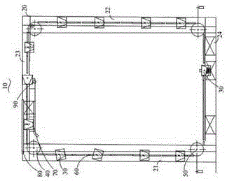
[0012] The circulation type steel ball mechanical transportation device provided by the present invention is applied in the waste heat boiler of the steel ball dedusting submerged arc furnace for transporting the steel balls.

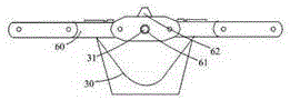
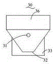
[0013] Such as figure 1 and figure 2 The circular steel ball mechanical transport device 10 includes a support frame 20, a steel ball transport bucket 30, and a driving wheel 40 fixed on the support frame 20, a driven wheel 50, a double chain 60, a fine adjustment correction plate 70, and a thick correction rod 80 , Mechanical unloading retaining wheel 90.

[0014] The support frame 20 includes a left vertical support frame 21, a right vertical support frame 22, an upper transverse support frame 23, and a lower transverse support frame 24. There is at least one driving wheel 40, and at least three driven wheels 50. The driving wheel 40 and the driven wheel 50 are all fixed on the support frame 20, for example, at the crossing position between the lef...


PUM


Abstract

The invention relates to a cyclic type mechanical conveying device for steel balls. The cyclic type mechanical conveying device comprises a supporting frame, a steel ball conveying hopper, a driving wheel, a driven wheel, two rows of chains, a fine adjustment correcting plate, a rough adjustment correcting rod and a mechanical discharge blocking wheel, wherein the driving wheel, the driven wheel, the two rows of chains, the fine adjustment correcting plate, the rough adjustment correcting rod and the mechanical discharge blocking wheel are fixed to the supporting frame. The fine adjustment correcting plate, the coarse adjustment correcting rod and the mechanical discharge blocking wheel are fixed to an upper transverse bearing frame. The fine adjustment correcting plate and the coarse adjustment correcting rod are arranged in parallel. The fine adjustment correcting plate is located below the coarse adjustment correcting rod. The distance between the fine adjustment correcting plate and the coarse adjustment correcting rod corresponds to the overall height of the steel ball conveying hopper. The steel ball conveying hopper containing steel balls makes contact with the fine adjustment correcting plate and the coarse adjustment correcting rod at first for horizontal correction and then makes contact with the mechanical discharge blocking wheel so as to provide overturning driving force through the mechanical discharge blocking wheel.

Description

technical field [0001] The invention relates to the technical field of waste heat boilers, in particular to a circulating steel ball mechanical transport device suitable for use in steel ball dust removal type submerged arc furnace waste heat boilers. Background technique [0002] Submerged arc furnaces are generally divided into three types of furnaces, the first is a fully enclosed type, the second is a semi-closed type with a low fume hood, and the third is an open type with a high fume hood. Because the semi-closed furnace contains very little combustible gas, the temperature is as high as 400 ° C, and more air is mixed in from the furnace door, and the amount of smoke is relatively large. It is suitable to use waste heat boilers for heat exchange and power generation, and the thermal efficiency can reach about 26% and 28%, but the difficulty is that most of the dust in the flue gas has a diameter of 0.1-0. Containing nano-sized particles, these particles show different...

Claims


Application Information

Patent Timeline
Patent Type & Authority Applications(China)
IPC IPC(8): B65G47/24
Inventor 李素梅
Owner 李素梅
Why Eureka
Try Eureka