Multi-angle milling and rotary clamping tool and operating method thereof

An operation method and multi-angle technology, applied in the field of mechanical processing tooling, can solve problems such as unstable workpiece holding, and achieve the effect of avoiding damage to the workpiece

Active Publication Date: 2017-04-19
MAANSHAN CHENXU MACHINERY MFG
View PDF8 Cites 1 Cited by
  • Summary
  • Abstract
  • Description
  • Claims
  • Application Information

AI Technical Summary

Problems solved by technology

[0007] Aiming at the problem of unstable workpiece clamping in the prior art, the present invention provides a multi-angle milling rotary clamping tool and its operation method

Method used


Image

  • Multi-angle milling and rotary clamping tool and operating method thereof
  • Multi-angle milling and rotary clamping tool and operating method thereof
  • Multi-angle milling and rotary clamping tool and operating method thereof

Examples


Embodiment 1

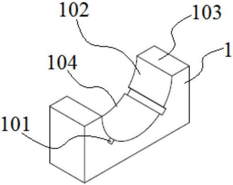
[0049] combine Figure 1-7 , The multi-angle milling rotary clamping tool of this embodiment includes a base 1, a clamp 2 and a positioning mechanism, the clamp 2 is located in the base 1, the clamp 2 and the base 1 cooperate with each other, and the positioning mechanism is stuck between the clamp 2 and the base 1.

[0050] The workpiece to be milled is placed in the fixture 2, the outside of the fixture 2 is wrapped by the base, and the positioning mechanism is stuck between the fixture 2 and the base 1, which plays a positioning role and prevents the fixture 2 from rotating in the circumferential direction relative to the base 1. For the purpose of fixing the workpiece, adjust the relative position of the fixture 2 and the base 1, and through the fixing function of the positioning mechanism, the fixed workpiece can be adjusted to rotate to different angles in the circumferential direction.

Embodiment 2

[0052] The multi-angle milling rotary clamping tool of this embodiment includes a base 1, a clamp 2 and a positioning mechanism, the clamp 2 is located in the base 1, the clamp 2 and the base 1 cooperate with each other, and the positioning mechanism is stuck between the clamp 2 and the base 1. The base 1 includes a raceway 104 and an upper end surface 103 of the base, the raceway 104 includes a raceway surface 102 of the base, the fixture 2 is placed on the raceway 104 of a base 1 , the raceway surface 102 of the base is in contact with The clamp 2 cooperates, and the raceway 104 of the other base 1 covers the clamp 2 .

[0053] The raceway 104 is semicircular, the base raceway surface 102 of the raceway 104 is a semicircular surface, and the clamp 2 is placed on the semicircular raceway 104 so that the clamp 2 rotates in the raceway 104, Change the angle of the workpiece in the circumferential direction, and then realize the milling of each surface of the workpiece.

[0054...

Embodiment 3

[0056] The multi-angle milling rotary clamping tool of this embodiment includes a base 1, a clamp 2 and a positioning mechanism, the clamp 2 is located in the base 1, the clamp 2 and the base 1 cooperate with each other, and the positioning mechanism is stuck between the clamp 2 and the base 1.

[0057] The base 1 includes a raceway 104 and an upper end surface 103 of the base, the raceway 104 includes a raceway surface 102 of the base, the fixture 2 is placed on the raceway 104 of a base 1 , the raceway surface 102 of the base is in contact with The clamp 2 cooperates, and the raceway 104 of the other base 1 covers the clamp 2 .

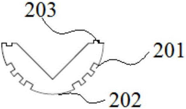
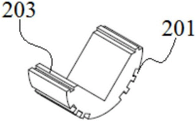
[0058] The fixture 2 includes a fixture raceway surface 202 and a fixture upper end surface 203, the fixture raceway surface 202 of one fixture 2 is matched with the base raceway surface 102 of a base 1, and the fixture raceway surface 202 of the other fixture 2 is matched with The base raceway surface 102 of the other base 1 is matched, and the cla...


PUM


Abstract

The invention discloses a multi-angle milling and rotary clamping tool and an operating method thereof, and belongs to the technical field of mechanical processing tools. The multi-angle milling and rotary clamping tool comprises bases, a clamp and a positioning mechanism, wherein the clamp is positioned in the bases; the clamp is mutually matched with the bases; the positioning mechanism is clamped between the clamp and the bases; each base comprises a roller path and a base upper end surface; the roller path comprises a base roller path surface; the clamp is arranged on the roller path of one base; the base roller path surface is matched with the clamp; the roller path of the other base covers the clamp; a to-be-milled workpiece is put into the clamp; the outer part of the clamp is covered by the bases; the positioning mechanism is clamped between the clamp and the bases to achieve positioning effect; relative positions of the clamp and the bases are regulated; and through fixing effect of the positioning mechanism, a fixed workpiece can be regulated to rotate to different angles in the peripheral direction. The multi-angle milling and rotary clamping tool can be used for clamping a to-be-processed workpiece without affecting surface precision of the workpiece, so that multi-angle processing of the workpiece is realized.

Description

technical field [0001] The invention relates to the technical field of machining tooling, in particular to a multi-angle milling rotary clamping tool and an operation method thereof. Background technique [0002] In the past, when milling various angles, the workpiece was fixed on the machine table, and different angle pads were used to mill various angles, or different angle tools were ground to process different angles, so that the processing time was long and the accuracy was high. It is difficult to guarantee that the number of clamping times is low, the efficiency is low, the symmetry of any two opposite surfaces is low, and the accuracy cannot meet the requirements. [0003] The workpiece needs to be positioned during the milling process, the surface of the workpiece has high requirements, and different parts need to be milled, and the workpiece needs to be converted from multiple angles. The clamping tooling in the prior art can generally play a role in the workpiece ...

Claims


Application Information

Patent Timeline
Patent Type & Authority Applications(China)
IPC IPC(8): B23Q3/06B23Q16/06
CPCB23Q3/06B23Q16/06B23Q2716/08
Inventor 成思福
Owner MAANSHAN CHENXU MACHINERY MFG
Why Eureka
Try Eureka