Electromagnetic flow meter

An electromagnetic flowmeter and flow rate technology, which is applied in the direction of detecting fluid flow, volume/mass flow generated by electromagnetic effects, testing/calibrating volume flow, etc., can solve problems such as unqualified electromagnetic flowmeters and achieve protection circuits. Effect

Inactive Publication Date: 2017-04-19
TECHCROSS
View PDF5 Cites 0 Cited by
  • Summary
  • Abstract
  • Description
  • Claims
  • Application Information

AI Technical Summary

Problems solved by technology

As a result, the impact transmitted to the motor and coil through the calandria is transmitted to the circuit of the electromagnetic flowmeter, so an unqualified electromagnetic flowmeter appears

Method used


Image

  • Electromagnetic flow meter
  • Electromagnetic flow meter
  • Electromagnetic flow meter

Examples


Embodiment Construction

[0031] Hereinafter, preferred embodiments of the present invention will be described in detail with reference to the accompanying drawings. First, reference symbols are attached to constituent elements in each drawing, and care should be taken to indicate the same constituent elements with the same reference numerals as much as possible even if they are shown in different drawings. In addition, when describing the present invention, when it is judged that a specific description of a related known configuration or function makes the gist of the present invention unclear, the description will be omitted. In addition, preferred embodiments of the present invention are described below, but the technical idea of ​​the present invention is not limited thereto, and of course can be modified and variously implemented by those skilled in the art.

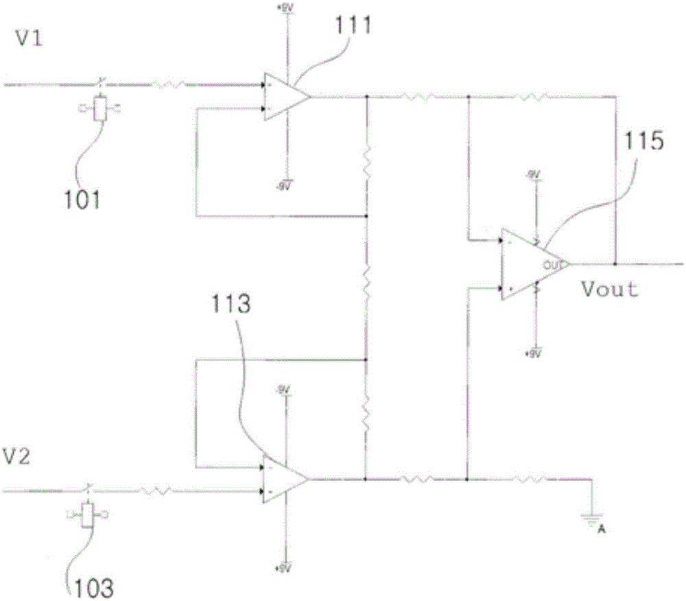
[0032] figure 2 It shows a relay part and an amplifying circuit part included in the electromagnetic flowmeter according to one embodimen...


PUM


Abstract

Provided is an electromagnetic flowmeter. The electromagnetic flowmeter includes: a coil configured to form a magnetic field as power is applied; an electrode configured to measure an electromotive force generated according to a flow rate passing through the magnetic field; an amplifying circuit unit configured to amplify the electromotive force measured at the electrode; and a relay unit which is provided between the electrode and the amplifying circuit unit and which is turned on or off. Therefore, the flow meter can be protected in the noise generated in the outside.

Description

technical field [0001] The present invention relates to an electromagnetic flowmeter, and more particularly, to an electromagnetic flowmeter capable of coping with external high-voltage shocks caused by lightning, welding, or the like. Background technique [0002] Electromagnetic flowmeter refers to a flowmeter that uses electromagnetic induction, and applies power to the coil to form a magnetic field perpendicular to the non-magnetic tube, and measures the flow by the following principle: If a conductive fluid flows in the tube, it is induced by electromagnetic induction between the two. The right-angled electrodes generate an electromotive force proportional to the flow rate. [0003] figure 1 The configuration of a general electromagnetic flowmeter is shown. [0004] Referring to the above drawings, the electromagnetic flowmeter 10 is installed on one side of the pipe 11 where the fluid flows, and includes a plurality of electrodes 12 arranged on the pipe 11 and a coil...

Claims


Application Information

Patent Timeline
Patent Type & Authority Applications(China)
IPC IPC(8): G01F1/58
CPCG01F1/58G01F1/60G01F1/588G01F25/10
Inventor 朴圭源金成泰李海敦李光镐
Owner TECHCROSS
Why Eureka
Try Eureka