BOOST direct-current boost short-circuit protection circuit

A short-circuit protection circuit and DC boost technology, applied in emergency protection circuit devices, electrical components, output power conversion devices, etc., can solve the problems of long-term short-circuit, poor versatility and high price

Active Publication Date: 2020-09-29
广东敏华电器有限公司
View PDF0 Cites 0 Cited by
  • Summary
  • Abstract
  • Description
  • Claims
  • Application Information

AI Technical Summary

Problems solved by technology

In order to protect the circuit, most of the market uses a dedicated micro-control system for protection, but the system is expensive and poor in versatility. There are also disposable fuses or self-recovery fuses that are directly connected in series in the main circuit, but this protection cannot be automatically restored. Do not short circuit for a long time

Method used


Image

  • BOOST direct-current boost short-circuit protection circuit
  • BOOST direct-current boost short-circuit protection circuit

Examples


Embodiment Construction

[0038] The present invention will be further described below in conjunction with specific embodiment:

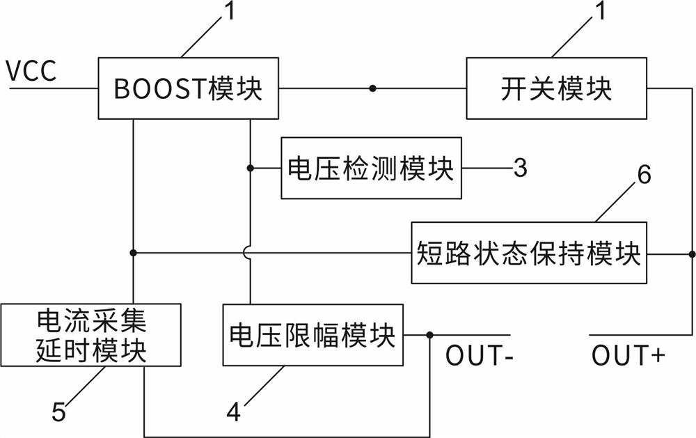
[0039] like figure 1 As shown, a BOOST DC boost short-circuit protection circuit includes a BOOST module 1, a switch module 2, a voltage detection module 3, a voltage limiting module 4, a current collection delay module 5 and a state holding module 6.

[0040] Among them, the switch module 2 , the voltage detection module 3 , the voltage limiter module 4 , the current collection delay module 5 and the state holding module 6 are respectively connected with the BOOST module 1 .

[0041] The voltage detection module 3 is connected to the switch module 2 and the voltage limiting module 4 respectively.

[0042] The flow acquisition delay module 5 is connected to the voltage detection module 3 and the state maintenance module 6 respectively.

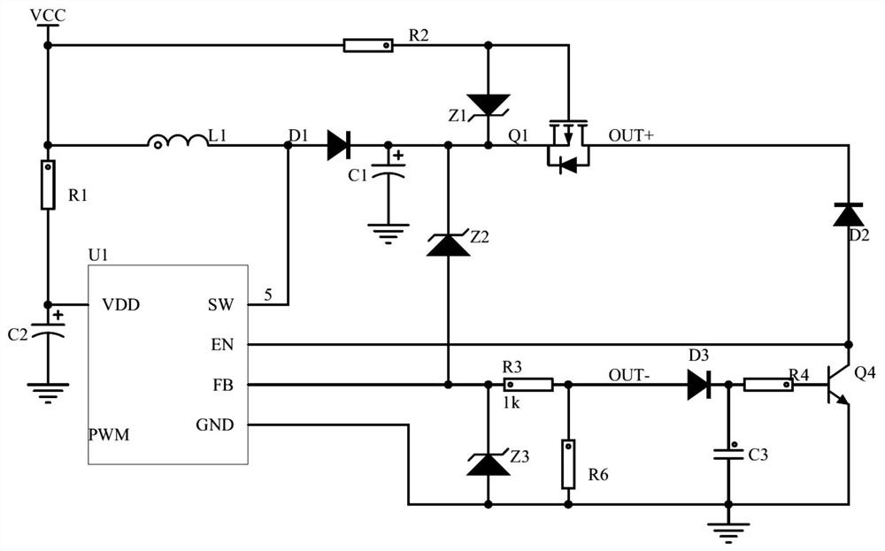
[0043] Specifically, as figure 2 As shown, the BOOST module 1 includes a PWM controller, a resistor R1, a boost inductor L1, a filter c...


PUM


Abstract

The invention discloses a BOOST direct-current boost short-circuit protection circuit. The BOOST direct-current boost short-circuit protection circuit comprises a BOOST module, a switch module connected with the BOOST module, a voltage detection module, a voltage amplitude limiting module, a current acquisition delay module and a state maintenance module, the voltage detection module is connectedwith the switch module and the voltage amplitude limiting module, the current acquisition delay module is connected with the voltage detection module and the state maintenance module. When the input voltage is equal to the output voltage, the switch module can be turned off, so that the output end has no voltage, and the risks of circuit protection, board explosion and combustion are avoided. Andwhen the load is short-circuited, the voltage amplitude limiting module can limit the amplitude of the peak voltage and then enter the BOOST module, so that the BOOST module is protected. And when theload is short-circuited, the BOOST module is closed, so that the BOOST module is protected. The state maintenance module can ensure that the BOOST module is at a low level continuously and is alwaysin a closed state when the output is in a continuous short circuit state.

Description

technical field [0001] The invention relates to the technical field of power electronics, in particular to a BOOST DC boost short-circuit protection circuit. Background technique [0002] In the field of power electronics technology, especially the BOOST DC boost circuit, since there is no relevant protection device between the input and the output, when the output short-circuits, it will damage the BOOST DC boost circuit, and even damage the power supply in severe cases. . In order to protect the circuit, most of the market uses a dedicated micro-control system for protection, but the system is expensive and poor in versatility. There are also disposable fuses or self-recovery fuses that are directly connected in series in the main circuit, but this protection cannot be automatically restored. Do not short circuit for a long time. SUMMARY OF THE INVENTION [0003] The purpose of the present invention is to overcome the deficiencies of the prior art and provide a BOOST d...

Claims


Application Information

Patent Timeline
IPC IPC(8): H02H7/12H02M1/32
CPCH02H7/1213H02M1/32
Inventor 黄美琼
Owner 广东敏华电器有限公司
Why Eureka
Try Eureka