Voltage triggering hardware locking and unlocking circuit

A technology of unlocking circuits and triggering circuits, which is applied in the direction of reliability improvement and modification, can solve the problems of low real-time performance and difficulty in realizing real-time control of circuits, and achieve the effect of protecting circuits and loads

Inactive Publication Date: 2013-09-25
ANHUI ACT BLUE ENVIRONMENTAL PROTECTION CO LTD
View PDF7 Cites 0 Cited by
  • Summary
  • Abstract
  • Description
  • Claims
  • Application Information

AI Technical Summary

Problems solved by technology

[0003] In the current hardware circuit, the state signal changes at any time with the change of the trigger signal. After the trigger signal disappears, the state signal also disappears; the real-time performance of the software control scheme is not high, and it is difficult to realize real-time control of the circuit.

Method used


Image

  • Voltage triggering hardware locking and unlocking circuit

Examples


Embodiment Construction

[0013] In order to make the technical means, creative features, goals and effects achieved by the present invention easy to understand, the present invention will be further described below in conjunction with specific illustrations.

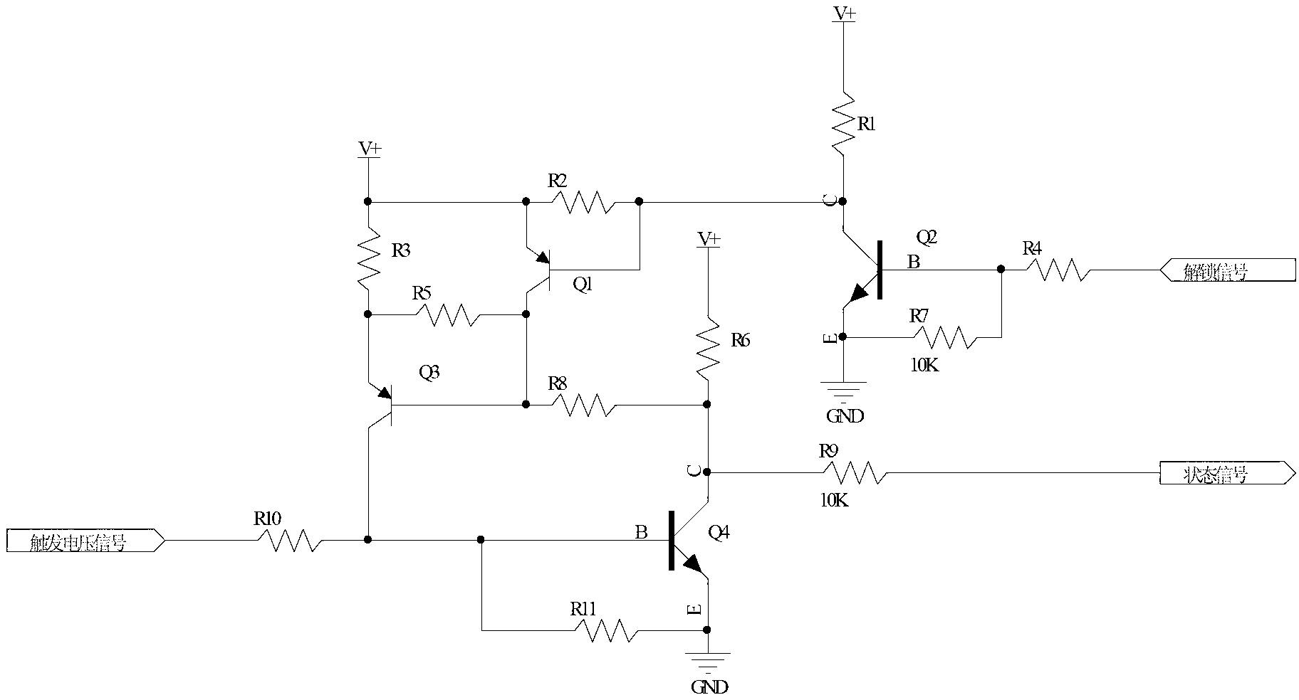
[0014] Refer below figure 1 Describe the present invention in detail, a voltage trigger hardware locking and unlocking circuit, including a voltage triggering circuit, a state locking circuit and an unlocking circuit. The voltage trigger circuit mainly includes transistor Q4 and resistors R6, R9, R10, R11. The base of Q4 is connected to the trigger voltage signal through resistor R10, the collector of Q4 is connected to the state signal through resistor R9, and connected to the power supply through resistor R6. The emitter is grounded, and the resistor R11 is connected in parallel between the base and emitter of Q4; the state lock circuit is composed of transistors Q1, Q3 and resistors R2, R3, R5, and R8, and the base collector of Q3 is connecte...


PUM


Abstract

The invention discloses a voltage triggering hardware locking and unlocking circuit which is formed by a voltage triggering circuit, a state locking circuit and an unlocking circuit. The voltage triggering circuit mainly comprises an audion Q4 and resistors, wherein a base electrode of the Q4 is connected with triggering voltage signals through the resistor R10, a collector electrode of the Q4 is connected with state signals through the resistor R9, and an emitting electrode of the Q4 is connected to the ground. The state locking circuit is formed by an audion Q1, an audion Q3 and a resistor, wherein a base electrode of the Q3 is connected with a collector electrode of the Q1, a collector electrode of the Q3 is connected with the base electrode of the Q4, and the base electrode and the collector electrode of the Q3 are in parallel connection with the resistor R5. The unlocking circuit is formed by an audion Q2 and a resistor, wherein a base electrode of the Q2 is connected with unlocking signals through the resistor R4, an emitting electrode of the Q2 is connected to the ground, and a collector electrode of the Q2 is connected with a base electrode of the Q1. The voltage triggering hardware locking and unlocking circuit is low in using cost, achieves the fact that the signals are rapidly triggered to the sate signals, and provides the unlocking signals.

Description

technical field [0001] The invention relates to the technical field of electric control, in particular to a voltage-triggered hardware locking and unlocking circuit. Background technique [0002] With the continuous improvement of the requirements for power conversion and processing in various fields of the national economy and the national defense industry, power semiconductor devices, which are the core components of power conversion devices, also play an increasingly important role. Power electronic devices form different power electronic circuits with different circuit topologies to realize various power conversion and control functions. In order to enable power electronic circuits to operate stably and provide excellent electrical energy, reliable control of power electronic devices is required. [0003] In the current hardware circuit, the state signal changes at any time with the change of the trigger signal. After the trigger signal disappears, the state signal ...

Claims


Application Information

Patent Timeline
Patent Type & Authority Applications(China)
IPC IPC(8): H03K19/003
Inventor 刘屹朱庆朱弢朱志强秦亮
Owner ANHUI ACT BLUE ENVIRONMENTAL PROTECTION CO LTD
Why Eureka
Try Eureka