Electronic device and control method thereof

a technology of electronic devices and control methods, applied in the direction of coupling device connections, power supply testing, instruments, etc., can solve problems such as the breakage of the internal circuitry connected to the vbus terminal of the electronic devi

Active Publication Date: 2021-12-07
CANON KK
View PDF22 Cites 0 Cited by
  • Summary
  • Abstract
  • Description
  • Claims
  • Application Information

AI Technical Summary

Benefits of technology

[0004]According to an aspect of the embodiments, an electronic device or a control method more improved than the electronic device or control method described above is provided.
[0005]According to an aspect of the embodiments, internal circuitry of the electronic device can be protected from an excessive voltage.

Problems solved by technology

If such an excessive voltage is applied to the VBUS terminal of the electronic device, it may cause internal circuitry connected to the VBUS terminal of the electronic device to break down.

Method used


Image

  • Electronic device and control method thereof
  • Electronic device and control method thereof
  • Electronic device and control method thereof

Examples


first embodiment

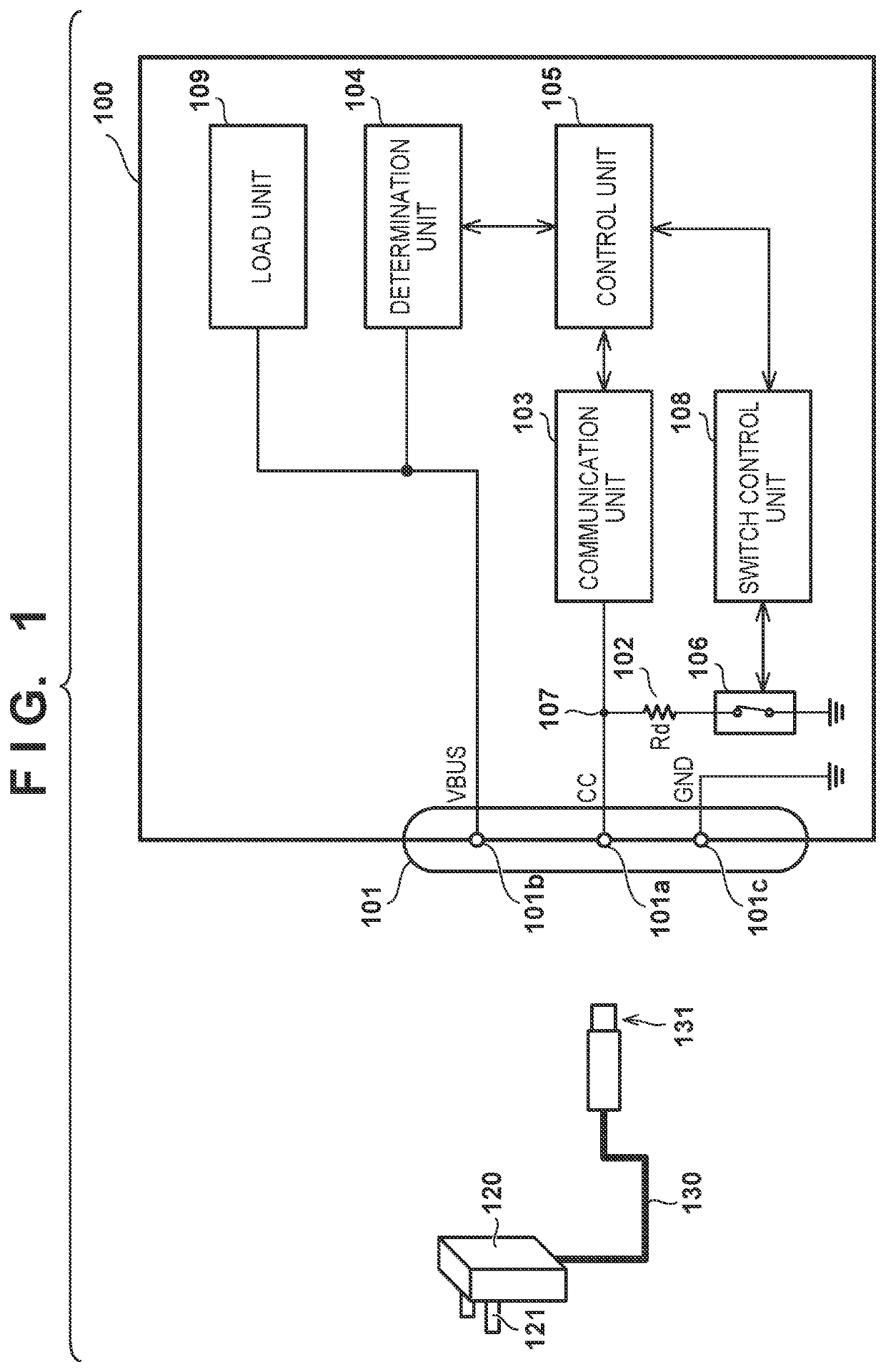
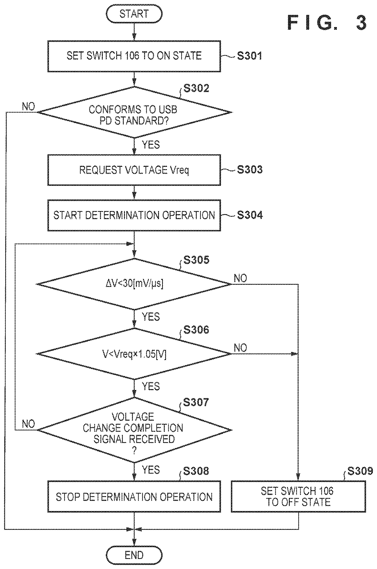
[0018]An example of components of an electronic device 100 according to the first embodiment will be described first with reference to FIG. 1. FIG. 1 is a block diagram for illustrating components of the electronic device 100 according to the first embodiment. The electronic device 100 is an electronic device capable of acting as an image capture apparatus or a mobile device.

[0019]As shown in FIG. 1, the electronic device 100 includes a connector 101, a pull-down resistor 102, a communication unit 103, a determination unit 104, a control unit 105, a switch 106, a switch control unit 108, a load unit 109, and a battery (not shown). The battery can be removed from the electronic device 100 by the user.

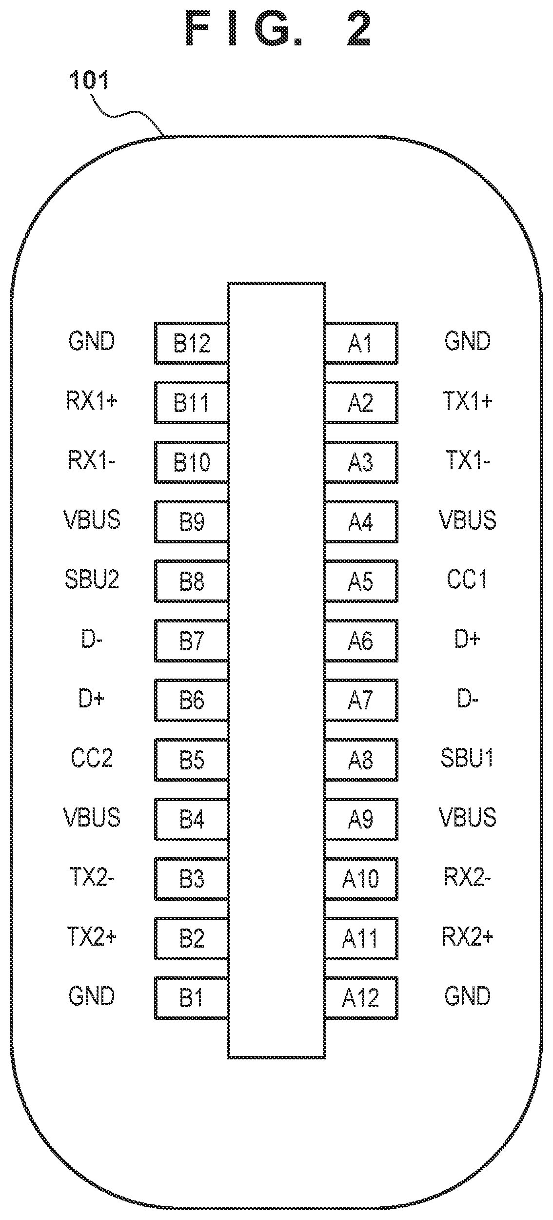
[0020]The connector 101 is a USB Type-C connector (receptacle) to which a plug 131 of a USB Type-C cable 130 is connected. In this specification, a connector conforming to USB (Universal Serial Bus) Type-C standard will be referred to as a USB Type-C connector, and a cable conforming to ...

second embodiment

[0075]Various kinds of functions, processes, or methods described in the first embodiment can be implemented by a personal computer, a microcomputer, a CPU (Central Processing Unit), a processor, or the like by using corresponding programs. In the second embodiment, a personal computer, a microcomputer, a CPU (Central Processing Unit), a processor, or the like will be referred to as a “computer X” hereinafter. Also, in the second embodiment, a program for controlling the computer X, that is, a program for implementing one of the various kinds of functions, processes, or methods described in the first embodiment will be referred to as a “program Y”.

[0076]Each of the various kinds of functions, processes, or methods described in the first embodiment is implemented by the computer X executing the program Y In this case, the program Y is supplied to the computer X via a computer-readable storage medium. The computer-readable storage medium according to the second embodiment includes at ...


PUM


Abstract

An electronic device includes a monitoring unit that monitors a voltage of a first terminal that receives power supplied from a power supply apparatus, and a control unit that performs control so as to stop the power supply from the power supply apparatus if a voltage variation per unit time of the first terminal is not less than a first predetermined value or the voltage of the first terminal is not less than a second predetermined value.

Description

BACKGROUNDField of the Invention[0001]Aspects of the disclosure generally relate to an electronic device and a control method thereof.Description of the Related Art[0002]A power supply apparatus (such as a personal computer, an AC-USB adapter, or the like) that includes a USB (Universal Serial Bus) interface can supply power, via a USB cable, to an electronic device that includes a USB interface, Japanese Patent Laid-Open No. 9-215176 discloses a method of setting a switch connected between an external power source and a load to a disconnected state when the voltage of the external power source is an overvoltage.[0003]A power supply apparatus conforming to USB Power Delivery (USB PD) standard can supply power of a maximum of 100 W (5 A, 20 V) to an electronic device through a USB interface. Hence, depending on the state or the arrangement of the power supply apparatus, an excessive voltage exceeding the maximum value of voltage that can be applied from the power supply apparatus to ...

Claims


Application Information

Patent Timeline
Patent Type & Authority Patents(United States)
IPC IPC(8): H02H3/00H02H3/20H02H1/00G06F1/28H02H3/44G06F13/42G06F1/30G01R31/40G01R19/12H01R24/60H01R107/00
CPCH02H3/20G06F1/28G06F1/30G06F13/4295H02H1/0007H02H1/0061H02H3/202H02H3/445G01R19/12G01R31/40G06F2213/0042G06F2213/3812G06F2213/3854H01R24/60H01R2107/00G06F1/305G06F1/266Y02E60/10G06F1/26
Inventor MORITOMO, HIROSHI
Owner CANON KK
Why Eureka
Try Eureka