
Main transformer and high voltage side cable zero-sequence differential protection polarity test circuit and method

A main transformer, polarity test technology, applied in the direction of instruments, measuring electricity, measuring electrical variables, etc., can solve the problems of inability to check the polarity correctness of zero-sequence differential protection devices, economic losses, malfunction and tripping, etc. The effect of preventing misoperation of zero-sequence differential protection and ensuring correctness

Active Publication Date: 2017-04-19
BAOSHAN IRON & STEEL CO LTD
View PDF5 Cites 9 Cited by
  • Summary
  • Abstract
  • Description
  • Claims
  • Application Information

AI Technical Summary

Problems solved by technology

The polarity test of the zero-sequence differential protection device is a troublesome problem, because when the generator G-main transformer MTR unit is in normal operation, there is only positive sequence current in the primary circuit of the protected equipment (main transformer and high-voltage side cable). , there is no zero-sequence current, so the load current cannot be used to verify the correctness of the polarity of the zero-sequence differential protection device
However, if the polarity test of the zero-sequence differential protection device of the main transformer and the high-voltage side cable is not carried out, accidents of tripping due to the wrong polarity of the zero-sequence differential protection device will often occur when the external system has a ground fault, resulting in economic loss

Method used


Image

  • Main transformer and high voltage side cable zero-sequence differential protection polarity test circuit and method
  • Main transformer and high voltage side cable zero-sequence differential protection polarity test circuit and method
  • Main transformer and high voltage side cable zero-sequence differential protection polarity test circuit and method

Examples


Embodiment

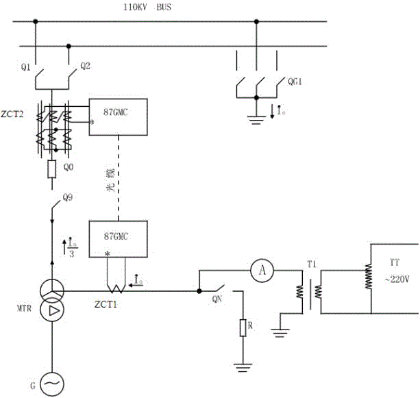
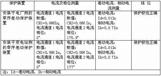
[0030] A factory imported a 350MW generator-transformer system, and installed an optical fiber differential main transformer and high-voltage side cable zero-sequence differential protection. According to the test circuit and test method of the present invention, the main transformer and high-voltage side cable zero-sequence differential For testing, see figure 2 , 40A current is injected from the front end of the neutral point grounding switch QN of the main transformer, and the data measured from the inside of the protection device 87GMC are shown in Table 1:

[0031] Table 1

[0032]

[0033] According to the test method of the present invention, the above-mentioned table 1 test data is analyzed, and it can be judged that the polarity of the main transformer and the high-voltage side cable zero-sequence differential protection device 87GMC is wrong, and after changing the wiring of the zero-sequence current transformer ZCT circuit on one side, The test was carried out ...


PUM


Abstract

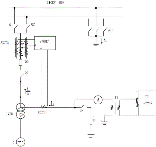
The invention discloses a main transformer and high voltage side cable zero-sequence differential protection polarity test circuit and method. According to the test circuit, a maintenance power supply is connected when a main transformer and a high voltage side bus are in the stop state, a single-phase voltage regulator is regulated and current is outputted to the appropriate value so that a current loop composed of the maintenance power supply-single-phase voltage regulator TT-isolation transformer TI-ammeter-main transformer high voltage side Y-shaped three-phase windings-main transformer high voltage side cable-main transformer high voltage side line knife Q9-GIS circuit breaker Q0-primary female knife Q1 (or secondary female knife Q2)-primary female grounding knife QG1 (or secondary female grounding knife)-grounding network-ground is formed. The current flows through the primary side of the first zero-sequence current mutual inductor ZCT1 and the second zero-sequence current mutual inductor ZCT2 of a zero-sequence differential protection device 87GMC so that simulation of zero-sequence current of the primary system in case of external grounding fault can be realized, and the polarity of the main transformer and the high voltage side cable zero-sequence differential protection device can be tested and inspected by the loop current.

Description

technical field [0001] The invention relates to a polarity test circuit and a test method for a main transformer and a high-voltage side cable zero-sequence differential protection polarity test circuit, and is suitable for the situation where the installation distance of ZCTs on both sides of the main transformer and the high-voltage side cable zero-sequence differential protection is relatively long. Background technique [0002] Main transformer and high-voltage side cable zero-sequence differential protection device 87GMC is used as the main protection when the main transformer high-voltage side Y-shaped winding and high-voltage side cables are grounded. With the characteristics of high ground fault sensitivity and fast action speed, the protection operates in 0 seconds when the unit stops completely, that is, trips the GIS circuit breaker on the high voltage side of the main transformer, the low voltage side switch of the plant general transformer, the magnetic field swi...

Claims


Application Information

Patent Timeline
IPC IPC(8): G01R31/02
CPCG01R31/50
Inventor 罗毅王丽华
Owner BAOSHAN IRON & STEEL CO LTD
Learn More