A jamming method for chirp radar

A linear frequency modulation and radar technology, which is applied in the reflection/re-radiation of radio waves, radio wave measurement systems, instruments, etc.

Active Publication Date: 2019-06-14
HOHAI UNIV
View PDF3 Cites 0 Cited by
  • Summary
  • Abstract
  • Description
  • Claims
  • Application Information

AI Technical Summary

Problems solved by technology

However, large time bandwidth and large bandwidth are often not compatible
That is to say, there is an irreconcilable contradiction between ranging accuracy and distance resolution, as well as speed measurement accuracy and speed resolution.

Method used


Image

  • A jamming method for chirp radar
  • A jamming method for chirp radar
  • A jamming method for chirp radar

Examples


Embodiment Construction

[0030] Below in conjunction with accompanying drawing and specific embodiment the technical solution of the present invention is described in further detail:

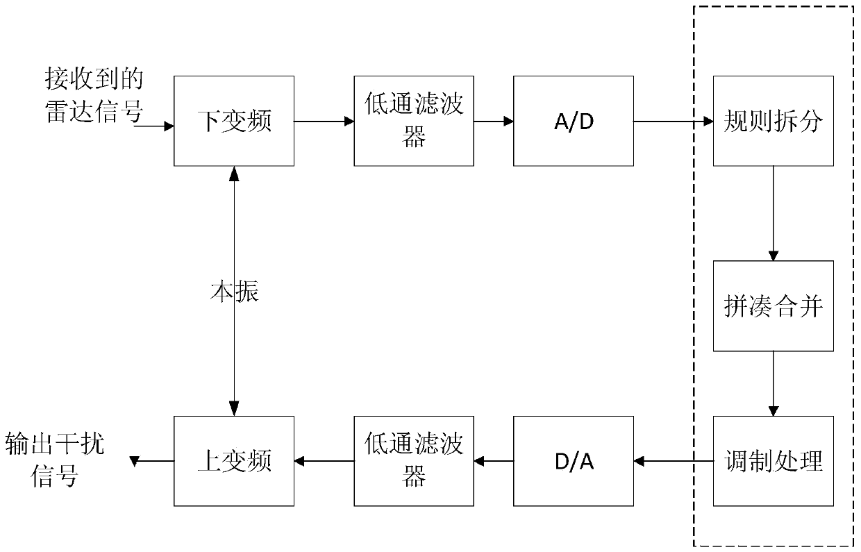
[0031] The present invention is a kind of jamming method aimed at chirp radar, such as figure 1 shown, including the following steps:

[0032] Step 1, the jammer receives the radar signal, and then converts the center frequency of the radar signal to a certain intermediate frequency or zero frequency through the frequency conversion of the mixer, and converts the received radar signal into a radar intermediate frequency signal;

[0033] Step 2, send the radar intermediate frequency signal to the A / D converter after passing through the low-pass filter, and sample it with a high-speed clock to obtain the radar pulse signal;

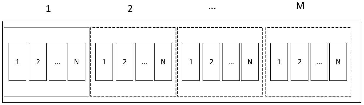
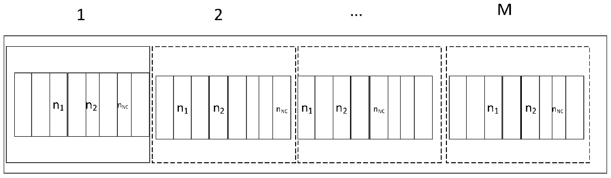
[0034] In step 3, the radar pulse signal obtained by high-speed sampling is regularly split, and then the split sub-pulse is assembled and merged according to certain rules, and finally the merged s...


PUM


Abstract

The invention discloses an interference method for a linear frequency modulation radar. The method provided by the invention comprises the steps that a jammer receives a radar signal, and converts the signal into an intermediate frequency signal through the down frequency conversion of a mixer; the radar intermediate frequency signal is sent into an A / D converter through a low-pass filter, and is sampled through a high speed clock; the sampled signal is rule-split; the split sub-pulse is modulated according to a certain rule; the modulated sub-pulse string is rule-merged; the merged pulse undergoes D / A conversion, and then is sent into the low-pass filter; and a signal after low-pass filtering is up-frequency-converted through the mixer to the center carrier frequency of the radar and is emitted. According to the invention, a sub-pulse string cycle forwarding working mode is used; a sub-pulse string signal and the radar signal contain the same frequency modulation slope, and match the matched filter of the radar signal; and a false target can be generated on the radar receiving end for cheating.

Description

technical field [0001] The invention relates to a jamming method for linear frequency modulation radar, which belongs to the field of radar electronic countermeasures. Background technique [0002] Using radar to detect and strike targets is an important means of modern military. Radar is an electronic system whose purpose is to detect targets and measure their range, angle and velocity. Radar transmits radio frequency pulses through an antenna and calculates range by measuring the time between the transmitted pulse and the echo of the target detected by the radar receiver. With the rapid development of radar technology, the requirements for radar operating range, resolution capability and measurement accuracy are getting higher and higher. We know that according to the resolution theory of radar signals, under the premise of ensuring a certain signal-to-noise ratio and achieving the best processing, the measurement accuracy and resolution have exactly the same requirement...

Claims


Application Information

Patent Timeline
Patent Type & Authority Patents(China)
IPC IPC(8): G01S7/38G01S13/50
CPCG01S7/38G01S13/50
Inventor 麻清华蒋德富
Owner HOHAI UNIV
Why Eureka
Try Eureka