Design method of variable inlet guide vane, and blade and compressor

A technology of guide vanes and design methods, applied in the field of compressors, can solve problems such as the range of available angles of attack of advanced aero-engines, and achieve the effect of meeting the requirements of structural integrity

Active Publication Date: 2017-04-19
BEIHANG UNIV
View PDF6 Cites 17 Cited by
  • Summary
  • Abstract
  • Description
  • Claims
  • Application Information

AI Technical Summary

Problems solved by technology

[0004] However, the flow in the inlet guide vane is an accelerated flow along the pressure gradient, and the NACA63-A4K6 series airfoil is modified from the compressor diffuser airfoil, so the airfoil proposed does not aim at the acceleration driven by the pressure gradient Flow, the most important flow characteristic, is fully considered
This makes the inlet guide vane designed with the NACA63-A4K6 series airfoil design have better performance than the inlet guide vane using the traditional subsonic compressor blade shape, but it cannot meet the needs of advanced aero-engines for a wider range of available angles of attack

Method used


Image

  • Design method of variable inlet guide vane, and blade and compressor
  • Design method of variable inlet guide vane, and blade and compressor
  • Design method of variable inlet guide vane, and blade and compressor

Examples


Embodiment Construction

[0061] The specific implementation manners of the present invention will be further described in detail below in conjunction with the accompanying drawings and embodiments. The following examples are used to illustrate the present invention, but are not intended to limit the scope of the present invention.

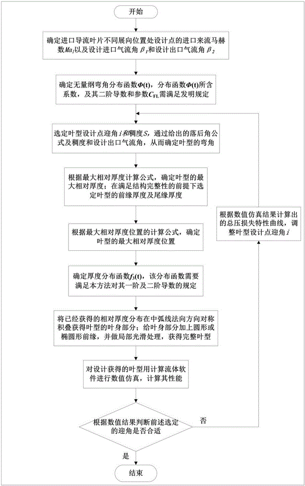
[0062] figure 1 The design flow chart of the variable inlet guide vane according to the present invention is shown. Such as figure 1 Shown, the design method of the variable inlet guide vane of the present invention, it comprises the following steps:

[0063] S1: Determine the inlet and incoming flow Mach number M at the design point at different spanwise positions of the inlet guide vanes a1 and the design inlet airflow angle β 1 and design outlet airflow angle β 2 , this step can be accomplished through conventional compressor flow design procedures. The consistency S of the primitive airfoil at the spanwise position can be determined from the flow-through results,...


PUM


Abstract

The invention relates to the technical field of compressors, and especially relates to a design method of a variable inlet guide vane. The design method comprises the following steps: step S1, determining an inflow Mach number and an inlet flow angle and an outlet flow angle; step S2, determining a dimensionless angular distribution function; step S3, selecting a design point angle of attack of a blade profile, and determining a bending angle of the blade profile; step S4, determining the maximum relative thickness, and the thickness of a leading edge and a trailing edge of the blade profile; step S5, determining the position of the maximum relative thickness of the blade profile; step S6, determining a thickness distribution function; step S7, symmetrically stacking to obtain a blade; step S8, adding the leading edge and the trailing edge to the blade part; and step S9, performing numerical simulation on the blade profile obtained in step S8, and calculating the performance of the blade profile and judging whether the blade profile is suitable. The invention further provides the design method, which expands the range of an available inlet angle of attack, and reduces the average total pressure loss coefficient in a whole working condition range. The invention further relates to the design method of the variable inlet guide vane, and the blade made by the method.

Description

technical field [0001] The invention relates to the technical field of compressors, in particular to a design method of a variable inlet guide vane and a vane made by the method, and also relates to a compressor comprising the vane. Background technique [0002] For most ground gas turbines and compressors for aero engines, inlet guide vanes are equipped to create the required inlet flow direction. When the adjustable inlet guide vane is working, as the speed of the compressor decreases, it will rotate to adjust the installation angle of the vane to provide the required outlet airflow angle. At this time, the angle of attack of the guide vane will increase greatly. The angle of attack will cause the airflow to pass through the blade to produce a large total pressure loss and boundary layer separation. A high total pressure loss coefficient will reduce the efficiency of the entire compressor, and the separation of the boundary layer may cause flutter of the downstream inlet ...

Claims


Application Information

Patent Timeline
Patent Type & Authority Applications(China)
IPC IPC(8): G06F17/50
CPCG06F30/17G06F30/20
Inventor 刘宝杰施恒涛于贤君
Owner BEIHANG UNIV
Why Eureka
Try Eureka