Device for cleaning roller surfaces of a drafting system device

A drafting and stripping device technology, applied in drafting equipment, textiles and papermaking, spinning machines, etc., can solve problems such as accumulation, affecting drafting operation, uneven fiber sliver, etc.

Active Publication Date: 2017-04-19
MASCHINENFABRIK RIETER AG
View PDF8 Cites 8 Cited by
  • Summary
  • Abstract
  • Description
  • Claims
  • Application Information

AI Technical Summary

Problems solved by technology

This in turn leads to an increase in the amount of material stripped by the stripping device per unit time
This can lead to the fact that currently known devices are no longer able to continuously remove stripped material (grime, fibers and other components mixed with honeydew) from the area of ​​the stripper
As a result, buildup can occur in this area and ultimately affect the drafting operation
As a result, on the one hand, the stripping function of the corresponding stripper is negatively affected, and on the other hand, when leaving the stripper, these deposits can enter the nip between the upper and lower rolls and thus have a negative impact on the drafting operation. Negative impact
This can lead to uneven fiber sliver formation downstream of the drafting system

Method used


Image

  • Device for cleaning roller surfaces of a drafting system device
  • Device for cleaning roller surfaces of a drafting system device
  • Device for cleaning roller surfaces of a drafting system device

Examples


Embodiment Construction

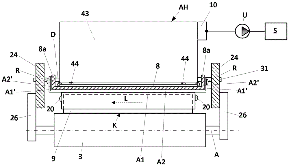
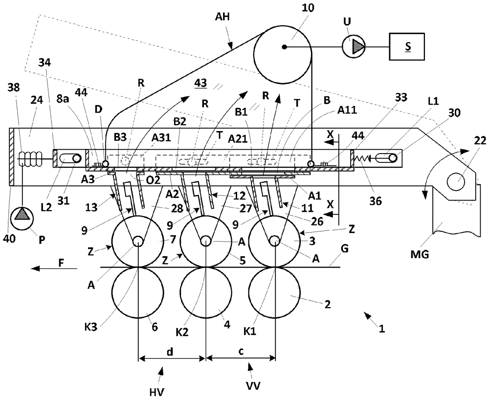
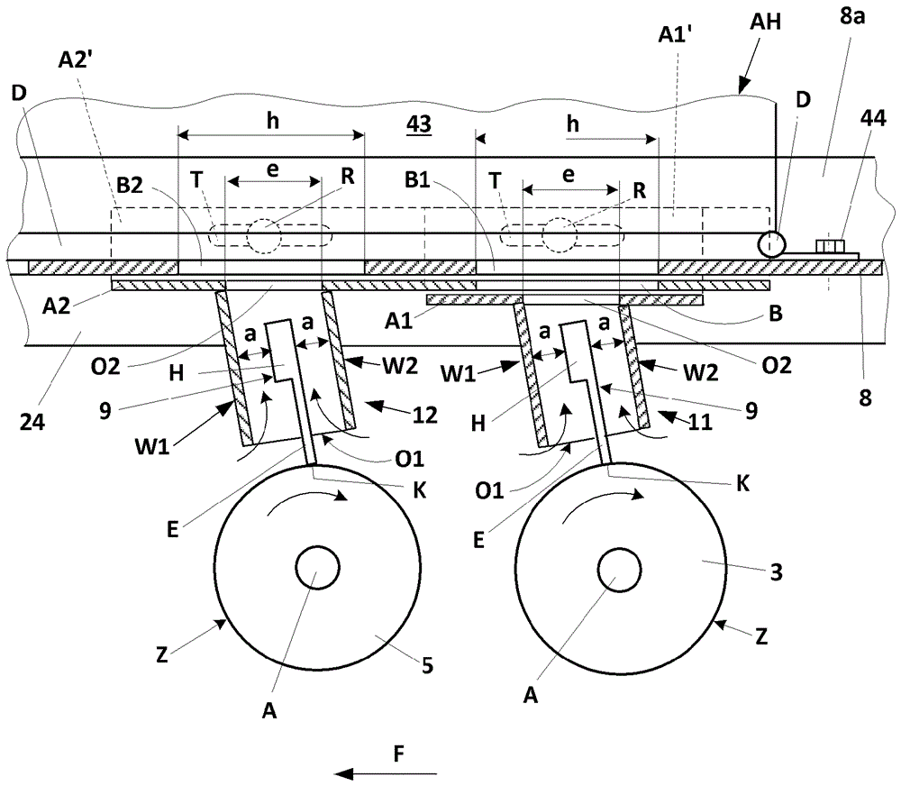
[0034] figure 1 Shows a schematic side view of the drafting system 1 equipped with roller pairs 2, 3; The fibrous material G is processed in zone HV. Here, the fibrous material G to be drawn is moved in the conveying direction F through the drafting system 1 . The lower rollers 2 , 4 , 6 , which are connected to a drive mechanism not shown, are generally embodied as profiled steel rollers and are rotatably mounted in the machine frame MG. The upper rolls 3, 5, 7 (also called pressure rolls) assigned to the lower rolls typically have a rubberized surface (circumferential surface) Z and are pressed against the appropriately assigned lower rolls 2, 4 during operation by means not shown Or 6 in order to form clamping positions K1, K2, K3. The upper rollers 3, 5, 7 are rotatably mounted via axis A in bearings 26, 27, 28 and are driven by friction by the respective lower rollers 2, 4, 6 cooperating therewith. Bearings 26 , 27 , 28 arranged on respective ends of the upper rollers...


PUM


Abstract

The invention relates to a device on a spinning preparation machine, said device comprising: a drawing frame (1) for processing a fibrous material (G) moved in a conveying direction (F) through the drawing frame; a number of roller pairs arranged behind one another having upper and lower rollers (2, 3; 4, 5; 6, 7); at least two longitudinal scraper devices (9), the respective scraper edges (K) of which abut one of the upper rollers (3, 5, 7) in order to remove dirt and other impurities; and a suction hood (AH) arranged above the scraper devices (9) and connected to a vacuum source (U). According to the invention, in order to avoid accumulations of stripped components in the region of the scraper devices, and in order to improve suction, each of the scraper devices (9) is attached to its own suction channel (11, 12, 13), wherein the scraper edge (K) of each scraper device (9) extends beyond the suction channel thereof in the region of a first opening (O1), and the individual suction channels are secured to a base wall (8) provided with openings (B1, B2, B3), wherein each suction channel (11, 12, 13) is provided with a second opening (O2) opposite the first opening (O1) and facing one of the openings (B1, B2, B3) of the base wall (8), wherein the suction hood (AH) extends beyond the openings (B1, B2, B3) of the base wall, and is attached to the side of the base wall (8) facing the suction channels (11, 12, 13).

Description

technical field [0001] The invention relates to a device on a spinning preparation machine having a drafting system with a plurality of roller pairs arranged one behind the other including upper and lower rollers, with at least two elongated stripping devices and There are suction hoods connected to a vacuum source arranged above the stripping devices, each of which is in contact with one of the upper rollers with its stripping edge. Background technique [0002] In order to remove dirt and other constituents deposited on the upper rolls of the drafting system during operation, stripping devices are used in practice, the stripping edges of which come into contact with the circumferential surface of the rolls with a certain pressing force. For example, flexible strippers are used which contact the circumference of the roller at a certain angle of attack and with a certain prestress. The flexible stripper is usually fastened to a holder by which it is fastened to the drafting...

Claims


Application Information

Patent Timeline
Patent Type & Authority Applications(China)
IPC IPC(8): D01H5/62
CPCD01H5/625
Inventor J.沃德鲁斯卡F.科勒L.彼得
Owner MASCHINENFABRIK RIETER AG
Why Eureka
Try Eureka