
Low-profile bidirectional locking large-angle universal pedicle screw

A pedicle screw and low-profile technology, applied in the field of pedicle screws, can solve the problems of inability to spread and compress, small universal mobility, difficult to connect rods, etc., and achieve firm and reliable locking and low difficulty in screw placement. , the effect of low adverse complications

Pending Publication Date: 2017-04-26
张衣北
View PDF9 Cites 6 Cited by
  • Summary
  • Abstract
  • Description
  • Claims
  • Application Information

AI Technical Summary

Problems solved by technology

However, the universal movement of the universal pedicle screw currently used is small, it is not easy to install the connecting rod, and the locking mechanism is realized by the mechanical pressure of a single clip, so it cannot be realized like the uniaxial pedicle screw. Parallel distraction and compression, not to mention rotation orthopedic, so only used to stabilize the spine
Even so, the notch of these screw caps after fixation is relatively high, and the position above the pedicle where the screw is placed is the most muscular position, which often leads to the long-term deterioration of the muscle tissue at the postoperative fixation site due to the high notch cap. Chronic low back pain due to friction injury

Method used


Image

  • Low-profile bidirectional locking large-angle universal pedicle screw
  • Low-profile bidirectional locking large-angle universal pedicle screw

Examples


Embodiment 1

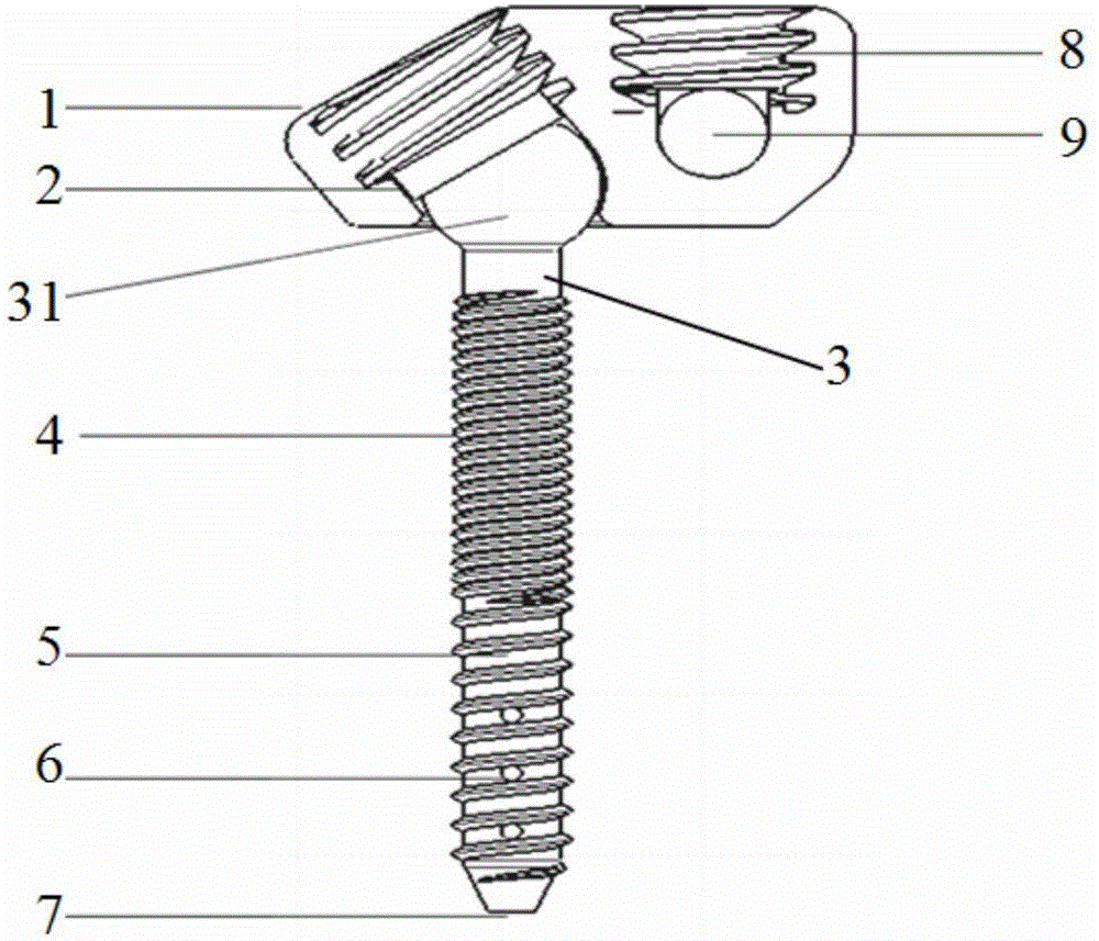
[0016] see figure 1 , Embodiment 1 of the present invention is provided with nail cap 1 and nail body 3, and the spherical nail head 31 side of nail body 3 is provided with U-shaped groove 9, and nail body 3 is hollow nail body, and the proximal end of nail body 3 is provided with near end thread 4, the distal end of the nail body 3 is provided with a distal thread 5, the depth of the proximal thread 4 is less than the depth of the distal thread 5, the distal thread 5 is provided with a through hole 6, and the distal thread 5 is used for injecting bone Cement, the end of the nail body 3 is provided with a hole 7, the hole 7 is used to inject bone cement, a nail cap and nail body two-way locking device 2 is provided between the nail cap 1 and the nail body 3, and a locking nut is provided on the U-shaped groove 9 8. The locking nut 8 is used for locking the U-shaped groove 9 and the connecting rod.

[0017] The nut 1 adopts a low profile nail cap.

[0018] U-shaped groove 9 i...

Embodiment 2

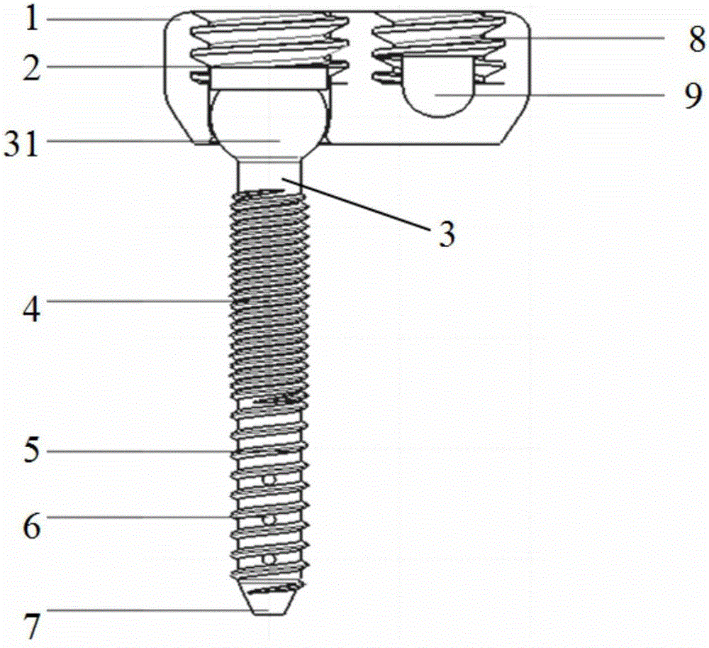
[0023] see figure 2 , similar to Embodiment 1, the difference is that the locking of the spherical nail head 31 of the nail body 3 and the nail cap 1 is locked by a large-sized nut, and the locking nut is larger in size, and the locking effect is better. At the same time, the U-shaped groove 9 and the connecting rod are locked and fastened by the locking nut 8 .


PUM


Abstract

The invention discloses a low-profile bidirectional locking large-angle universal pedicle screw and relates to pedicle screws for spinal posterior approach surgery. The low-profile bidirectional locking large-angle universal pedicle screw for fixation and correction through pedicle nailing during spinal posterior fixation and correction surgery is provided. The pedicle screw comprises a screw cap and a screw body, wherein a U-shaped groove is formed in the side of a spherical screw head of the screw body; the screw body is hollow; a proximal thread is formed in the proximal end of the screw body; a distal thread is formed in the distal end of the screw body; the depth of the proximal thread is smaller than the depth of the distal thread; a through hole is formed in the distal thread; the distal thread is used for injecting bone cement; a pore is formed in the tail end of the screw body and is used for injecting the bone cement; a screw cap and screw body bidirectional locking device is arranged between the screw cap and the screw body; and a locking nut is arranged on the U-shaped groove and is used for locking the U-shaped groove and a connecting rod.

Description

technical field [0001] The invention relates to a pedicle screw for posterior spinal surgery, in particular to a large-angle universal pedicle screw with a low profile and two-way locking. Background technique [0002] Posterior spinal surgery is a commonly used surgical method. When it comes to fixation or correction, the screw-rod internal fixation system is essential. This screw-rod system is usually composed of pedicle screws and their fasteners and connecting rods. At present, pedicle screws can be basically divided into two types, namely, uniaxial fixed pedicle screws and multiaxial universal pedicle screws. screw. When the uniaxial pedicle screw is used for fixation, the technical requirements for screw placement are very high. If the U-shaped grooves of the two screws are not parallel, the connecting rod and the U-shaped groove will change from surface contact to point contact, resulting in stress concentration and easy screw breakage. Or the rod is broken; if more...

Claims


Application Information

Patent Timeline
IPC IPC(8): A61B17/70
CPCA61B17/7034A61B17/704A61B17/7064A61B17/7074
Inventor 张衣北
Owner 张衣北
Learn More