Explosion-initiating constant-current ignition module for initiating explosive device

A technology of pyrotechnics and emitters, applied in the field of electronics, can solve problems such as increased difficulty, and achieve the effects of short debugging time, simple operation and high reliability

Active Publication Date: 2017-04-26
SHENZHEN AEROSPACE NEW POWER TECH
View PDF4 Cites 10 Cited by
  • Summary
  • Abstract
  • Description
  • Claims
  • Application Information

AI Technical Summary

Problems solved by technology

Therefore, the selection and replacement of current-limiting resistors is a very cumbersome process, which virtually increases the difficulty for the development of pyrotechnic controllers.

Method used


Image

  • Explosion-initiating constant-current ignition module for initiating explosive device
  • Explosion-initiating constant-current ignition module for initiating explosive device
  • Explosion-initiating constant-current ignition module for initiating explosive device

Examples


Embodiment Construction

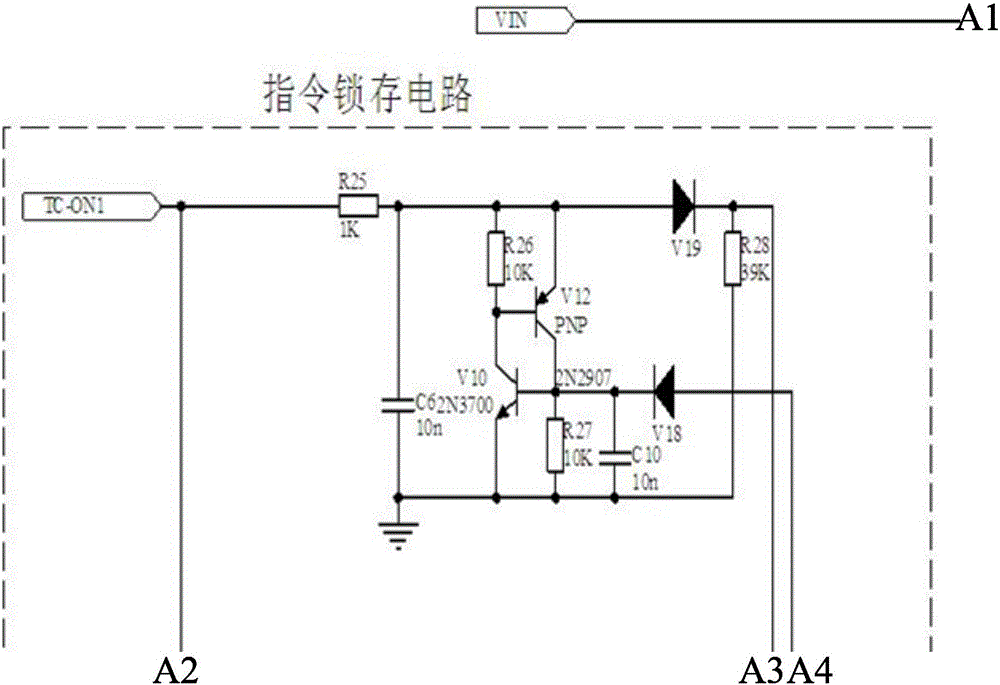
[0013] Such as Figure 3-10 As shown, the present invention discloses a constant current ignition module for pyrotechnic detonation, including a front-stage current-limiting circuit and a rear-stage current-limiting circuit. The front-stage current-limiting circuit includes a current-limiting circuit, a drive and a power circuit. The current limiting circuit includes resistor R1*, resistor R2*, R3*, R4*, R5*, R6*, transistor V1, resistor R4, transistor V2, resistor R5, one end of resistor R1* is connected to the bus input VIN, and the other end of resistor R1* One end is connected to the source of MOS tube V26, resistors R2*, R3*, R4*, R5*, R6* are connected in parallel with R1*, the emitter of triode V1 is connected to the bus input VIN, the base of triode V1 is connected to one end of resistor R4, and the triode The collector of V1 is connected to the emitter of triode V2, the other end of resistor R4 is connected to the source of MOS tube V26, the base of triode V2 is conne...


PUM


Abstract

The invention provides an explosion-initiating constant-current ignition module for an initiating explosive device. The explosion-initiating constant-current ignition module comprises a preceding-stage current-limiting circuit and a backward-stage current-limiting circuit, and the preceding-stage current-limiting circuit and the backward-stage current-limiting circuit each comprises a current-limiting circuit and a drive and power circuit. The explosion-initiating constant-current ignition module for the initiating explosive device has the beneficial effects that a solid-state switch MOSFET is selected as a constant-current protection switch to be used for replacing an ignition circuit in former spacecraft initiating explosive devices, constant-current working can be conducted according to instructions, an instruction fault tolerance function is achieved, adjusting and current-limiting resistor replacing are not needed, multiple paths of initiating devices can share one ignition module, and the explosion-initiating constant-current ignition module is a restorable and reusable ignition circuit product. Therefore, the explosion-initiating constant-current ignition module has the advantages of being easy to operate, short in production and adjusting time, high in reliability and the like.

Description

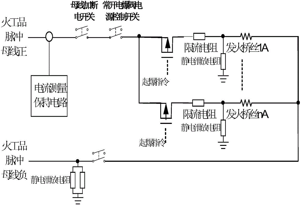
technical field [0001] The invention relates to the field of electronics, in particular to a constant-current ignition module for pyrotechnic detonation. Background technique [0002] At present, domestic pyrotechnic detonation devices are generally composed of relays, MOS tubes, and current-limiting resistors. figure 1 It is a schematic diagram of the working principle of the pyrotechnic detonation device of my country's satellites at present, and only one bus bar is shown in the figure. There are three magnetic latching relays on the detonation line as the power-on and power-off switches of the busbar and the return line and the control switch of the normally open electric explosion valve, and the four electronic switches are used as four insurances for the pyrotechnic detonation device, which can effectively prevent any one of them. False detonation caused by misoperation. Using the Hall current sensor as the measuring element of the detonation current requires the meas...

Claims


Application Information

Patent Timeline
Patent Type & Authority Applications(China)
IPC IPC(8): F42D1/05
CPCF42D1/05
Inventor 张贤涛程航
Owner SHENZHEN AEROSPACE NEW POWER TECH
Why Eureka
Try Eureka