
Method and device for identifying motor moment of inertia and motor control device

A technology of moment of inertia and identification method, which is applied in the fields of identification of moment of inertia of motors and devices and motor control devices, can solve problems such as complex process, large amount of calculation, and failure of identification, and achieve the effect of simple method, small amount of calculation, and easy realization

Active Publication Date: 2019-04-02
SHANGHAI MITSUBISHI ELEVATOR CO LTD
View PDF11 Cites 0 Cited by
  • Summary
  • Abstract
  • Description
  • Claims
  • Application Information

AI Technical Summary

Problems solved by technology

[0003] In the Chinese invention patent application with the application number 200810018783.0, the moment of inertia of the AC servo system is identified by using the average motor speed during the acceleration and deceleration movement of the servo system, the average torque of the servo system, and the total time of system acceleration and deceleration, but this method requires The load torque is symmetrical when the AC servo system is accelerating and decelerating, and the moment of inertia must remain unchanged during the identification process, otherwise the identification will fail
In the Chinese invention patent CN101699763B, the motor is first accelerated to the first speed with the first acceleration, then accelerated to the second speed with the second acceleration, then decelerated to the first speed with the third acceleration, and finally decelerated to zero with the fourth acceleration speed, and use the output torque, speed and acceleration and deceleration time of the motor in the above process to identify the moment of inertia, but this method changes the normal speed control pattern of the motor drive system, and the process is complicated and the identification period is long
Chinese invention patent CN102209677B obtains the inertia error before convergence through the integral calculation of the speed deviation between the model speed and the actual speed in the continuous period of the acceleration state and uniform acceleration state of the elevator car, and then predicts the inertia error after convergence according to the calculation results , and finally use the prediction results to correct the moment of inertia, but this technical solution is cumbersome and complex, with a large amount of calculation, and requires a continuous interval between the jerk state and the uniform acceleration state during the operation of the motor, which limits the operation mode of the motor; in addition, the In the derivation of the scheme, the disturbance torque is assumed to be a constant value, which also constitutes an important limitation for the implementation of the technical scheme

Method used


Image

  • Method and device for identifying motor moment of inertia and motor control device
  • Method and device for identifying motor moment of inertia and motor control device
  • Method and device for identifying motor moment of inertia and motor control device

Examples


Embodiment 1

[0055] For PMSM, when using i d = 0 control strategy, its output torque T e with its torque current i q Satisfy the following relationship:

[0056] T e = K t i q (4)

[0057] Among them, K t is the torque coefficient of the motor, i q is the q-axis component of the stator current of the motor.

[0058] Substituting formula (4) into formula (2), after sorting, we get:

[0059]

[0060] For the dynamic system shown in formula (5), the real-time observation There are many methods, such as using Extended State Observer (ESO) (refer to "Active Disturbance Rejection Control Technology - Control Technology for Estimating and Compensating Uncertainty Factors", Han Jingqing, 2013, National Defense Industry Press), equivalent input disturbance observation (Rui-Juan Liu et al., Active Disturbance RejectionControl Based on an Improved Equivalent-Input-Disturbance Approach, IEEE / AMSETran.On Mechatronics, P1410~1413, Vol.18, No.4, August 2013) and unknown input observer ( G...

Embodiment 2

[0085] This embodiment is similar to Embodiment 1, and only the differences will be described below.

[0086] Compared with Embodiment 1, the motor moment of inertia identification device 15e of this embodiment omits the acceleration calculator for calculating the angular acceleration of the motor.

[0087] Carry out bilateral integration on formula (12) and formula (13) respectively to get:

[0088]

[0089]

[0090] Considering that the moment of inertia of the elevator drive motor is approximately a constant value, there are:

[0091]

[0092]

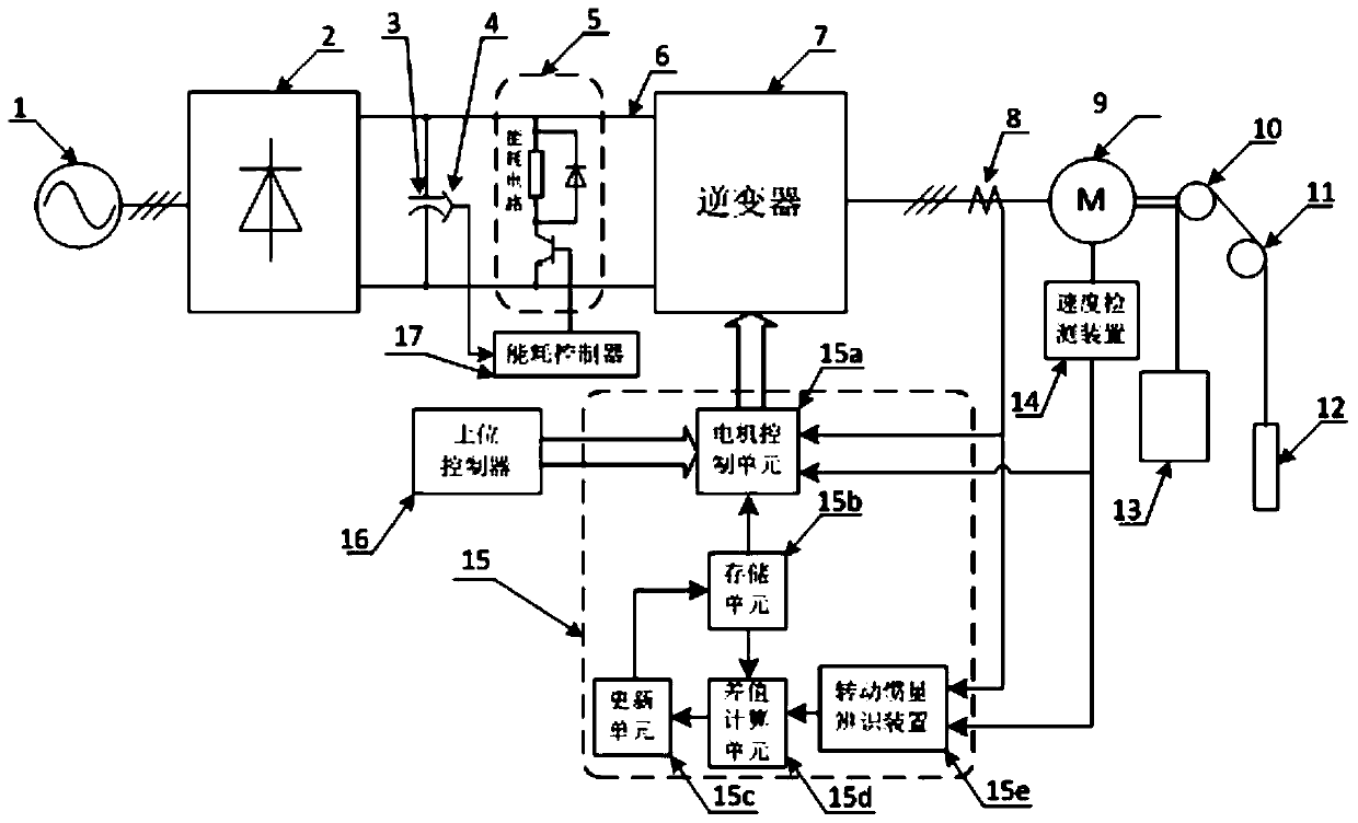
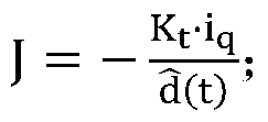
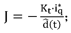
[0093] In the formula, J is the moment of inertia of the motor speed control system, K t is the torque coefficient of the motor, is the torque current command value of the motor, i q is the q-axis current obtained after the motor stator current detected by the current detection device 8 undergoes appropriate coordinate transformation, is the disturbance torque observation result output by the disturbance torque obs...

Embodiment 3

[0096] This embodiment is similar to Embodiment 1, and only the differences will be described below.

[0097] Compared with Embodiment 1, the motor moment of inertia identification device 15e of this embodiment omits the acceleration calculator for calculating the angular acceleration of the motor.

[0098] When elevator drive motor 9 was in motor zero speed or when running at a constant speed, Formula (12) and formula (13) then become:

[0099]

[0100]

[0101] When the moment of inertia recognizer is in the zero-speed or uniform-speed motion state of the elevator, according to the disturbance torque observation result and the torque current value i output by the disturbance torque observer q Calculate the moment of inertia of the motor according to formula (18), or according to the disturbance torque observation result and torque current command value output by the disturbance torque observer Calculate the moment of inertia of the motor according to formula (19). ...


PUM


Abstract

The invention discloses a motor moment-of-inertia identification method and device. The moment of inertia of a motor is calculated according to a real-time observation result, obtained by a disturbance torque observer, of disturbance torque in a motor motion equation, acceleration information and torque current of the motor or torque current instruction value. The identification method and device can realize online real-time identification of the moment of inertia of the motor without influencing driving performance of the motor or limiting operation mode of the motor. The invention also provides a motor control device using the motor moment-of-inertia identification device above.

Description

technical field [0001] The invention relates to motor technology, in particular to an on-line identification method and device for the moment of inertia of a motor and a motor control device using the on-line identification device. Background technique [0002] Moment of Inertia (Moment of Inertia) is the measure of inertia when a rigid body rotates around its axis (the characteristic that a rotating object maintains its uniform circular motion or static), usually expressed by the letter I or J. In engineering practice, the motor as the driving torque provider in the motor drive system and the load as the driven body have the problem of mutual cooperation between the driving and the driven body. The design basis of the control parameters of the driving motor controller usually includes There is a moment of inertia that depends on the motor load. When the moment of inertia of the motor load changes while the control parameters of the controller remain unchanged, the performa...

Claims


Application Information

Patent Timeline
Patent Type & Authority Patents(China)
IPC IPC(8): H02P23/14H02P23/12
Inventor 陈玉东张筱马红星况飞飞
Owner SHANGHAI MITSUBISHI ELEVATOR CO LTD
Learn More