Dynamic equilibrium adjusting valve

A technology of dynamic balance and regulating valves, which is applied in the direction of balance valves, lifting valves, safety valves, etc., and can solve problems such as hydraulic imbalance, system hydraulic imbalance, troubles, etc.

Active Publication Date: 2017-05-03
常州汉腾自动化设备有限公司
View PDF6 Cites 5 Cited by
  • Summary
  • Abstract
  • Description
  • Claims
  • Application Information

AI Technical Summary

Problems solved by technology

However, when the acting pressure of the most unfavorable loop is guaranteed, the acting pressure of other nodes may be much higher than the design value, which will lead to the hydraulic imbalance of the system
In addition, excessive or improper selection of the water pump will also cause the operating flow to deviate from the design value, which will lead to hydraulic imbalance in the system
And the problem of water conservancy imbalance in the pipe network will cause a lot of waste of energy, increase of operating noise and shorten the service life of equipment
[0003] In order to reduce or eliminate the phenomenon of hydraulic imbalance in the pipe network, it is necessary to continuously debug the system. This method is not only troublesome and time-consuming, but more importantly, this adjustment is lagging behind. disordered phenomenon
In the traditional technology, there is still a solution to this problem by using a dynamic flow balance valve, but this kind of dynamic flow balance valve uses a rubber diaphragm as a pressure balance member. In an environment with poor water quality or high pressure, the rubber diaphragm Susceptible to damage resulting in loss of functionality of the dynamic flow balancing valve
[0004] To sum up, in the traditional technology, the flow regulation effect of the pipe network is not ideal. Therefore, how to improve the flow regulation effect of the pipe network has become a technical problem to be solved urgently by those skilled in the art.

Method used


Image

  • Dynamic equilibrium adjusting valve
  • Dynamic equilibrium adjusting valve
  • Dynamic equilibrium adjusting valve

Examples


Embodiment Construction

[0036] In order to enable those skilled in the art to better understand the technical solutions of the present invention, the present invention will be further described in detail with reference to the accompanying drawings.

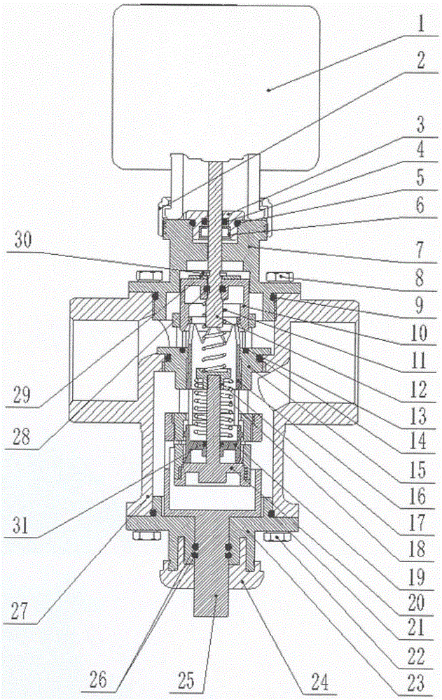
[0037] Please refer to Figure 1-12 , The embodiment of the present invention provides a dynamic balance regulating valve, which is used to regulate the water flow of the pipeline. The dynamic balance regulating valve includes a valve body 27 and a valve core. The valve body usually has a valve body top cover 7 and a valve body bottom cover 23. The valve body top cover 7 and the valve body bottom cover 23 are detachable and fixed to facilitate the installation of the valve core. The valve body top cover 7 can be fixed to the top of the valve body 27 by a top cover screw and a gasket 8, and a top cover sealing ring 9 is arranged between the valve body top cover 7 and the valve body 27 to ensure the sealing of the connection. The valve body bottom cover 23 ...


PUM


Abstract

The invention discloses a dynamic equilibrium adjusting valve. The dynamic equilibrium adjusting valve comprises a valve body and a valve element mounted in a valve cavity of the valve body. The valve cavity comprises a water inlet cavity and a water outlet cavity which are sealed and partitioned. The valve element comprises an outer barrel fixedly connected with the valve body, an inner barrel slidably arranged in the outer barrel, and a valve element bottom cover fixed to the bottom of the outer barrel. A pressure sensing plate is arranged at the bottom of the inner barrel. The outer barrel is provided with a water inlet communicating with the water inlet cavity and a water outlet communicating with the water outlet cavity. An inner cavity of the outer barrel serves as a water channel communicating with the water inlet and the water outlet. A flow equilibrium port is formed in the side wall of the inner barrel and can adjust the flowing area of the water outlet along with sliding of the inner barrel relative to the outer barrel. The valve element bottom cover is provided with a central column penetrating through the pressure sensing plate. A fixing base is fixed to the top end of the central column. An elastic part is arranged between the fixing base and the pressure sensing plate. A pressure sensing cavity communicating with the water inlet cavity is formed between the valve element bottom cover and the pressure sensing plate. According to the scheme, the flow adjusting effect of pipe networks can be improved, and stable flow is ensured.

Description

Technical field [0001] The invention relates to the technical field of valve design, in particular to a dynamic balance regulating valve. Background technique [0002] In the variable flow water system of the different pipeline network for fluid transmission and distribution, the system pressure needs to be designed according to the resistance of the loop, usually only based on the resistance of the most unfavorable loop. However, when the working pressure of the most unfavorable loop is guaranteed, the working pressure of other nodes may be much larger than the design value, which will cause the hydraulic imbalance of the system. In addition, excessive or improper selection of the water pump will also cause the operating flow to deviate from the design value, which will lead to the system's hydraulic imbalance. The occurrence of water imbalance in the pipeline network will cause a large amount of waste of energy, increase in operating noise and shorten the service life of equip...

Claims


Application Information

Patent Timeline
Patent Type & Authority Applications(China)
IPC IPC(8): F16K17/30F16K1/36F16K37/00
CPCF16K1/36F16K17/30F16K37/0016
Inventor 刘勇郭建翔李海清高国友
Owner 常州汉腾自动化设备有限公司
Why Eureka
Try Eureka