Disc feeding machine

A technology of feeding machine and disc, applied in the field of automatic feeding device, can solve the problems of bearing ring damage, bearing ring being automatically turned over, etc., to achieve the effect of not easy to damage

Inactive Publication Date: 2017-08-18
海宁上通优必胜轴承有限公司
View PDF12 Cites 3 Cited by
  • Summary
  • Abstract
  • Description
  • Claims
  • Application Information

AI Technical Summary

Problems solved by technology

[0004] like image 3 The bearing ring shown in the figure includes a large end face and a small end face. The thickness of the small end face is greater than the thickness of the large end face. When loading materials, the large end face must be placed downward, otherwise the bearing sleeve will be damaged during processing. The ring will be damaged by the cutter. When using the above-mentioned disc loading machine as image 3 When loading the bearing rings shown, the operator will pour a large amount of unprocessed bearing rings into the disc feeder, and there may be bearing rings placed upside down, while the above disc feeder The upside-down bearing ring cannot be turned over automatically, so that the bearing ring is prone to damage during processing

Method used


Image

  • Disc feeding machine
  • Disc feeding machine
  • Disc feeding machine

Examples


Embodiment Construction

[0027] The present invention will be described in further detail below in conjunction with the accompanying drawings.

[0028] This specific embodiment is only an explanation of the present invention, and it is not a limitation of the present invention. Those skilled in the art can make modifications to this embodiment without creative contribution as required after reading this specification, but as long as they are within the rights of the present invention All claims are protected by patent law.

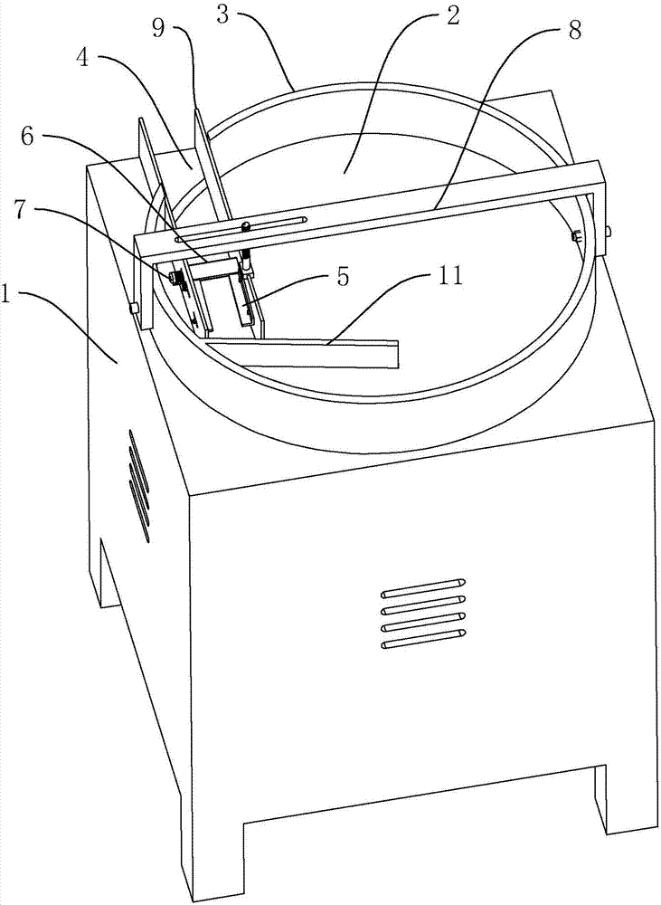
[0029] Such as figure 1 As shown, a disc loading machine includes a frame 1, on which a disc body 2 is horizontally rotatably arranged, and on the frame 1 is provided with an outer frame 3 arranged around the disc body 2, the outer frame 3 There is a feeding channel 4 that communicates with its inner and outer space. The feeding channel 4 is composed of two guide plates 9. A frame body 8 is provided on the frame 1. The two guide plates 9 are provided with a frame body away from ...


PUM


Abstract

The invention discloses a disc feeding machine. The disc feeding machine comprises a rack, a disc body arranged on the rack in a rotating manner, a frame arranged around the disc body, a material conveying channel communicating with internal and external space of the frame, and a forward and reversely rotating motor for driving the disc body to rotate. Guide plates used for guiding a bearing ring placed reversely to slide upwards in an inclining manner are arranged on the opposite inner walls of the material conveying channel correspondingly. The guide plates are arranged upwards in an inclining manner in the discharging direction of the material conveying channel. Turnover plates used for pushing the bearing ring to be turned over are arranged between the two guide plates in a rotating manner. A drive motor for driving the turnover plates to rotate is arranged on the material conveying channel. According to the disc feeding machine, the bearing ring placed reversely can be turned over, and the phenomenon that the bearing ring is damaged in the machining process does not occur easily.

Description

technical field [0001] The invention relates to an automatic feeding device, more specifically, it relates to a disc feeding machine. Background technique [0002] In the assembly line of industrial production such as bearing processing, the continuous operation of the processing device requires continuous supply of materials, and manual feeding is time-consuming and laborious. At present, bulk materials generally use disc feeders to realize automatic feeding. [0003] The announcement number is: the Chinese patent of CN203921898U discloses a kind of disc feeding machine, comprises disc, the outer frame that surrounds disc, the feedway that is arranged on one side of disc, the frame that is positioned at disc below and is arranged on machine. A motor in the frame and connected to the disc axis, the material channel includes a feed port located on the disc and a discharge port located outside the disc, the material channel includes a material channel plate A and a material c...

Claims


Application Information

Patent Timeline
Patent Type & Authority Applications(China)
IPC IPC(8): B65G47/80B65G47/248
CPCB65G47/248B65G47/80
Inventor 陈炳华张明杰
Owner 海宁上通优必胜轴承有限公司
Why Eureka
Try Eureka