A device and method for realizing the positioning of a moving platform
A motion table and reflection module technology, applied in the field of integrated circuit equipment manufacturing, can solve the problems of low capture accuracy, increase the cost of the whole machine, etc., and achieve the effect of high capture repeatability
- Summary
- Abstract
- Description
- Claims
- Application Information
AI Technical Summary
Problems solved by technology
Method used
Image
Examples
Embodiment 1
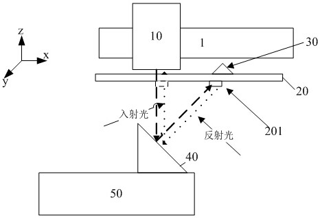
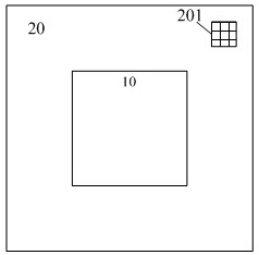
[0041] The device for realizing the positioning of the moving platform provided by the present invention includes an illumination light source, an image sensor 10 , a reference plate 20 , a corner prism 30 and a reflector 40 . Such as figure 1 As shown, the image sensor 10 is fixed under the main substrate 1 of the lithography apparatus, and its optical axis direction is vertically downward. In this embodiment, the image sensor 10 is a CCD or CMOS; Overlapping light beams; the reference plate 20 is fixed under the main substrate 1, the reference plate 20 is a transparent plate, and a measurement mark 201 is arranged, and the present embodiment selects a square mark, such as figure 2 As shown; the light beam provided by the illumination source illuminates the measurement mark 201 to form a measurement mark image; the corner prism 30 is fixed on the reference plate 20, and is arranged behind the measurement mark 201 to reflect the measurement mark image; the reflector 40 is a p...
Embodiment 2
[0044] The motion table 50 has six degrees of freedom. In order to position the six degrees of freedom (translation, vertical, rotation, and tilt) of the motion table 50, it is necessary to set a plurality of measurement marks 201 on the reference plate 20, correspondingly on the motion table 50. To set up multiple mirrors.
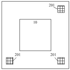
[0045] Such as image 3 In the example shown, the difference between this embodiment and Embodiment 1 is that three measurement marks 201 are set on the reference plate, respectively distributed in the first, third, and fourth quadrants, and correspondingly, they are also arranged on the motion table 50 Three reflection mirrors 40, three reflection mirrors 40 are respectively arranged in the first, third and fourth quadrants of the moving platform 50, as Figure 4 shown.
[0046]The information of the measurement marker image measured by the image sensor 10 has two degrees of freedom, and when the motion platform 50 degrees of freedom moves, it will aff...
Embodiment 3
[0048] Different from Embodiment 2, in this embodiment, all three mirrors 40 are arranged in the first quadrant to reduce the movement time of the moving platform 50 in the positioning process, specifically as Figure 5 As shown, here the reflector 40 is a plane mirror installed on the moving platform 50 at an inclination angle of 60°, and the normal vectors of the three plane mirrors are respectively [1, 1, sqrt (6)], [-1, -1, sqrt (6)], [1,-1, sqrt(6)].
[0049] The following is a method for realizing the positioning of the moving platform provided by the present invention.
[0050] For aligning a single measurement mark 201, there is the following conversion relationship:
[0051]
[0052] in:
[0053] xi, yi: measure the measured value of the two-dimensional position information of the marker image for the image sensor;
[0054] xi0, yi0: measure the measured value of the marker image during calibration;
[0055] Gij: the conversion matrix from the degree of freedom...
PUM
 Abstract
Description
Claims
Application Information
 - R&D
- Intellectual Property
- Life Sciences
- Materials
- Tech Scout
- Unparalleled Data Quality
- Higher Quality Content
- 60% Fewer Hallucinations
Browse by: Latest US Patents, China's latest patents, Technical Efficacy Thesaurus, Application Domain, Technology Topic, Popular Technical Reports.
© 2025 PatSnap. All rights reserved.Legal|Privacy policy|Modern Slavery Act Transparency Statement|Sitemap|About US| Contact US: help@patsnap.com


