Supercharge Your Innovation With Domain-Expert AI Agents!

Video matrix control apparatus and video matrix control method

A technology for video matrix and control equipment, applied in the direction of digital output to display equipment, TV, color TV, etc.

Active Publication Date: 2017-05-03
ATEN INT CO
View PDF4 Cites 9 Cited by
  • Summary
  • Abstract
  • Description
  • Claims
  • Application Information

AI Technical Summary

Problems solved by technology

Therefore, if you do not use a web page but need a graphical interface to set the video matrix (video matrix), there seems to be no solution at present

Method used


Image

  • Video matrix control apparatus and video matrix control method
  • Video matrix control apparatus and video matrix control method
  • Video matrix control apparatus and video matrix control method

Examples


Embodiment Construction

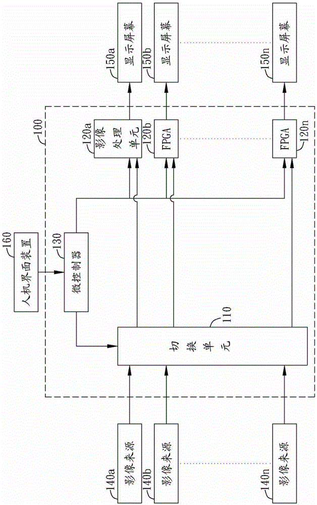
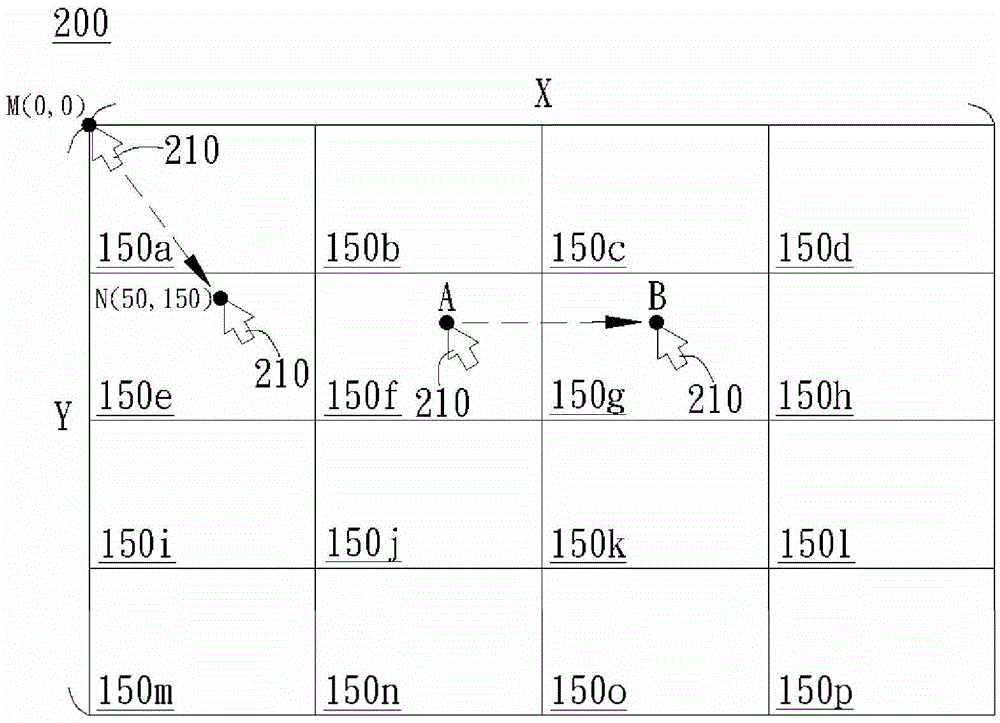
[0034] Please refer to figure 1 and figure 2 , figure 1 It is a schematic diagram of a video matrix control device in a preferred embodiment of the present invention, figure 2 A schematic diagram of a TV wall. like figure 1 As shown, the video matrix control device 100 of the present invention includes a switching unit 110 , a plurality of image processing units 120 a - 120 n and a microcontroller 130 . The switching unit 110 is used to receive multiple video signals from multiple video sources 140a-140n, and switch the video signals from the video sources 140a-140n to the corresponding video processing units 120a-120n according to the control signal from the microcontroller 130. , wherein the switching unit 110 includes a multiplexer, and the image sources 140a-140n include but are not limited to televisions, computers, digital video recorders or cameras.

[0035] The image processing units 120a-120n are coupled to the switching unit 110 and are respectively coupled to...


PUM


Abstract

A video matrix control apparatus is disclosed, which includes a switch, a microcontroller, and a plurality of video processors. The switch receives video signals from the video sources. The video processors are coupled to the switch and corresponded to a plurality of display screens respectively, wherein the display screens form a TV wall. The microcontroller defines an absolute coordinate area of the TV wall. When the microcontroller receives an operation signal from a human interface device, the microcontroller generates a control signal according to a coordinate position within the absolute coordinate area corresponding to the operation signal, and transmits the control signal to the switch and at least one video processor, so that the video processor generates an operation screen and a cursor to be displayed on the TV wall, and the TV wall can be set to operate by operating the cursor on the operation screen through the human interface device.

Description

technical field [0001] The present invention relates to a control device, and in particular to a video matrix control device. Background technique [0002] The TV wall is a plurality of display devices combined in a matrix type (matrix). Generally speaking, the prior art utilizes a video wall system device or a video matrix control apparatus, which receives all input videos combined by several display devices and uses individual screens of the combined screens to show demand. For example, the individual video contents of all display devices are firstly processed, and then transmitted to the corresponding display devices in an appropriate format to display images. A certain display image belongs to a certain display component of the overall display of the video wall, and is integrated in the video wall All the display components of the system become an overall display screen of a complete TV wall. [0003] Because the traditional technology can only set the TV wall by webp...

Claims


Application Information

Patent Timeline
IPC IPC(8): H04N5/268G06F3/14
CPCG06F3/1446H04N5/268
Inventor 朱弘棋
Owner ATEN INT CO
Features
  • R&D
  • Intellectual Property
  • Life Sciences
  • Materials
  • Tech Scout
  • Unparalleled Data Quality
  • Higher Quality Content
  • 60% Fewer Hallucinations
Learn More